Right Atrium
Venous blood returns to the heart via the
superior and inferior vena cave into the right atrium, where
it is stored during right ventricular systole. During ventricular
diastole, blood flows from the right atrium into the right ventricle
(Figs. 1, 2, 4, 7, 8, 9 ). The right atrium forms the right
lateral cardiac border and is above, behind, and to the right
of the right ventricle (Figs. 4 and 7). Most of the right atrium
is to the right and anterior to the left atrium (Figs. 4 and
7). Anteromedially, the right atrial appendage protrudes from
the right atrium and overlaps the aortic root (Figs. 1 and 2).
On the posterior external surface of the right atrium a ridge,
the sulcus Terminalis (or terminal groove), extends vertically
from the superior to the inferior vena cava. This corresponds
to an internal muscular bundle, the crista terminalis, which
runs along the edge of the entrance to the right atrial appendage
to the front of the orifice of the superior vena cava and then
to the right side of the inferior vena cava (Figs. 8, 9). The
sinus node is usually located at the lateral margin of the junction
of the superior vena cava with the right atrium and the atrial
appendage, beneath or near the sulcus terminalis (terminal groove)
(Figs. 1 and 2).
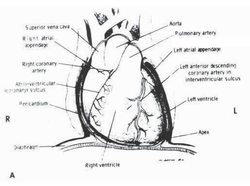
A. Diagram
showing the normal relations of the pericardium, great vessels,
ventricles, and the atria as viewed in the frontal position.
R= right; L= left. (Diagram by
McClaren Johnson, Jr., M.D.)
FIGURE 1
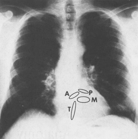
B. Frontal (AP) roentgenogram
of the heart. The components that form the cardiac silhouette
can be readily identified from A above. A= aortic valve ring;
P= pulmonary valve ring; M= mitral valve ring; T= tricuspid
valve ring. Reference: Hurst’s
THE HEART, Eighth Edition, pages 60-61.
FIGURE 1
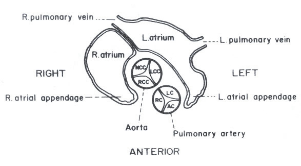
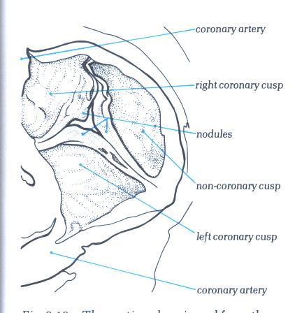
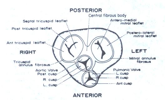
C. Schematic transverse section through
the heart at approximately the level of the second intercostal
space. The relation between the left and the right atria and
the interatrial septum is illustrated. The relative positions
of the aortic and pulmonary valves and their cusps are shown.
AC = anterior cusp; RC = right cusp; LC = left cusp; RCC = right
coronary cusp; NCC = noncoronary cusp of the aortic valve.
FIGURE 1
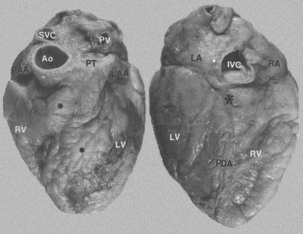
FIGURE 2:
External views of the heart
A. Anterior surface showing epicardial
fat*, which obscures the interventricular sulci containing the
left anterior descending artery. Ao = aorta; LAA = left atrial
appendage; LV = left ventricle; PT = pulmonary trunk; PV = pulmonary
vein; RAA= right atrial appendage; RV= right ventricle; SVC
= superior vena cava.
B. Posterior
surface of heart showing location of the posterior descending
artery (PDA), crux of the heart *, and inferior vena cava (IVC).
LA = left atrium; RA= right atrium. Reference:
Hurst’s THE HEART, Eighth Edition, page 61.
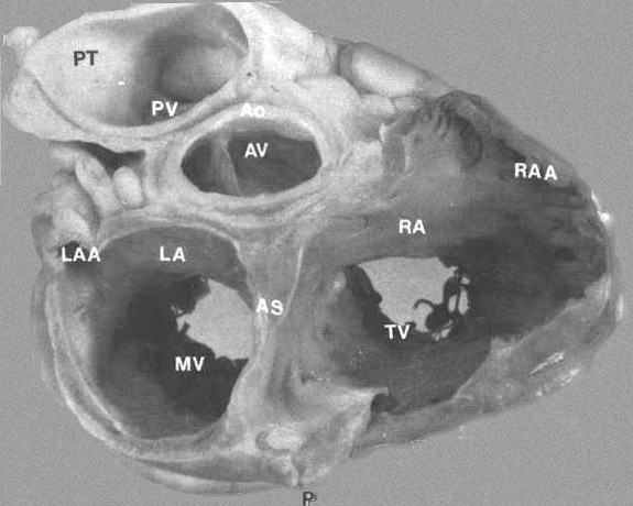
FIGURE 3:
Transverse section through base of heart showing relationship
of various chambers and great vessels. A = anterior; AO = aorta;
AS = atrial septum; AV = aorta; LA = left atrium; LAA = left
atrial appendage; MV = mitral valve; RA = right atrium; RAA
= right atrial appendage; P = posterior; PT = pulmonary trunk;
PV = pulmonary trunk; PV = pulmonic valve; TV = tricuspid valve.
From Hurst’s THE Heart, Eighth edition, page 61.)
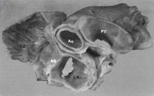
FIGURE
4: Basal view of heart
showing relationship of great vessels and atria. The left atrium
(LA) has a smooth endocardium while the right atrium (RA) is
trabeculated. The aorta (Ao) is posterior to the pulmonary trunk
(PT) but anterior to the atrial septum (AS).
The
Morphologically Right Atrium
In the normal heart, this structure forms
the rightward and anterior part of the cardiac mass, overlapping
the right hand margin of the left atrium and communicating with
the right ventricle to its right side (fig. 4.10a). Externally,
the chamber consists of a posterior part which receives the
superior and inferior venae cavae termed the sinus venarum (fig.
4.10b) and an anterior part which extends forwards in pouch-like
fashion to encircle the right border of the aorta, the right
atrial appendage (fig. 4.10c). The border between the two is
marked by a groove, the sulcus terminalis (fig. 4.10b) which
is variably developed and in some hearts may be inconspicuous.
The left hand margin of the right atrium is marked posteriorly
by the groove between the superior vena cava and the right pulmonary
vein (fig.4.10d). Beneath the groove, the left border of the
inferior vena cava is in the same plane as the atrial septum,
running inferiorly to the crux cordis. Superiorly, the roof
the atrium curves posteriorly behind the aorta, a small groove
sometimes being seen at the site of the septum, to become continuous
with the left atrial wall (fig.4.10c).
(The color pictures and their corresponding
sketches in the following descriptions of the right and left
atria are from Cardiac Anatomy,1980, by R.H.Anderson and Anton
E. Becker)
Fig.4-10a:
- The heart in its in situ position dissected to show the position
of the right atrium and the right ventricle.
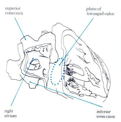
Diagram - Fig.4-10a-1
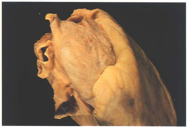
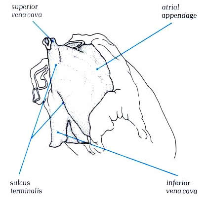
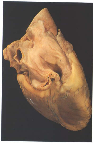
Figure 4.10b:
The heart viewed from the right
showing how the great veins open into the posterior part of
the right atrial chamber. The anterior part, the atrial appendage,
is seen extending round the aorta.
Schematic -
Fig.4-10b-1
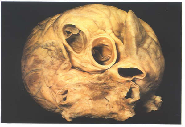
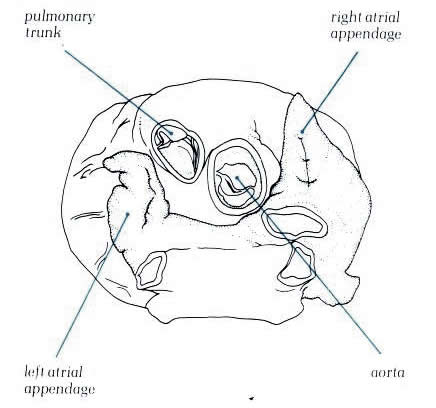
Figure 4.10c:
The heart viewed from above showing
how the atrial appendages encircle the roots of the great arteries
(Left atrial appendage; aorta; pulmonary trunk; right atrial
appendage)
Schematic - Figure
4.10c-1
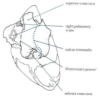
Figure
4.10d: The heart viewed
posteriorly and from the right showing the groove between the
pulmonary veins and right atrium: sulcus terminalis, ‘Waterston's
groove’, inferior vena cava, right pulmonary veins, superior
vena cava.
Schematic -
Figure 4.10d-1
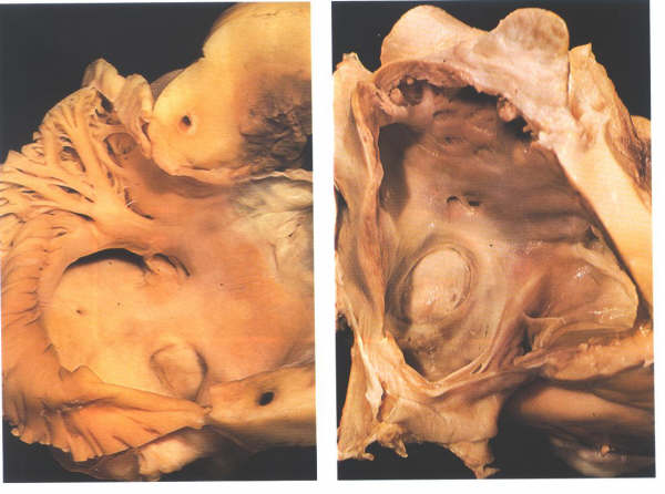
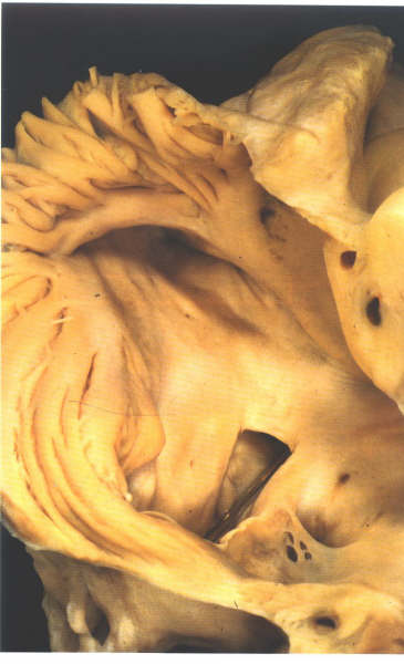
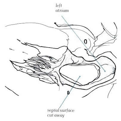
Figure
4.10e:
When the atrium is opened, the distinction between the posterior
smooth-walled sinus venarum and the anterior trabeculated appendage
is much more readily apparent (fig. 4.10e-1). The junction between
the two is marked by a well-formed muscle bundle, the crista
terminalis (fig. 4.10e-1). The trabeculae tend to run at right
angles to the crista. The inside of the right atrial chamber
presents a posterior surface, a septal surface, and an anterior
surface. The floor of the chamber can be considered as tricuspid
valve orifice orientated obliquely to the right (fig. 4.10e-2)
although the inferior vena cava opens into the junction of the
posterior wall and the floor.
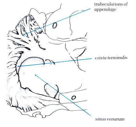
Schematic -
Figure 4.10e-1:
Dissection of the right atrium
viewed from the front showing the crista terminalis separating
the posterior smooth wall sinus venarium and the trabeculated
atrial appendage
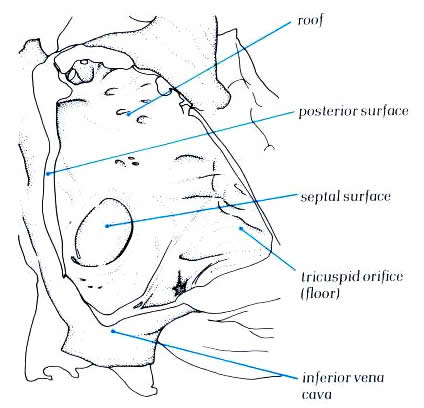
Schematic -
Figure 4.10e-2:
The right atrium viewed from
the right following removal of the parietal wall and showing
its surfaces.
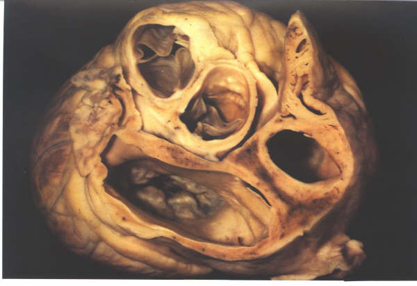
Figure 4.10f:
- Section through the short axis of the atrial chambers showing
oblique orientation of the atrial septum
When the atrium is opened, the distinction
between the posterior smooth-walled sinus venarum and the anterior
trabeculated appendage is much more readily apparent (fig. 4.10e-1).
The junction between the two is marked by a well-formed muscle
bundle, the crista terminalis (fig. 4.10e-1). The trabeculae
tend to run at right angles to the crista. The inside of the
right atrial chamber presents a posterior surface, a septal
surface, and an anterior surface. The floor of the chamber can
be considered as tricuspid valve orifice orientated obliquely
to the right (fig. 4.10e-2) although the inferior vena cava
opens into the junction of the posterior wall and the floor.
The superior vena cava orifice is in the roof of the chamber,
and the septal surface is obliquely orientated, running from
a right posterior to left anterior position (fig 4.10f).
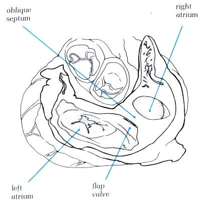
Diagram -
4.10f-1: - Figure 4.10f
with labelling of structures.
The crista terminalis runs from the anterior
part of the septal surface and swings in front of the orifice
of the superior vena cava which enters the right atrium between
the crista and the superior limbus of the fossa ovalis (figure4.10g).Having
skirted the superior caval orifice, the crista turns down the
right side of the inferior vena cava and curves in toward the
tricuspid orifice, passing beneath the ostium of the coronary
sinus (fig.4.10h. The margin of the crista terminalis is reinforced
in the fetal life by sheet-like structures which separate the
orifices of the inferior vena cava from the atrial appendage.
These become the valves of the inferior vena cava (Eustachian
valve) and the coronary sinus (Thebesian valve) and may be seen
to variable extent in the adult heart. The Thebesian valve is
usually reasonably formed, but the Eustachian valve is less
well formed (fig.4.10g-2).Fibrous strands may exist between
the various parts of the crista which extend across the cavity
of the right atrium.They, like the valves, are remnants of the
extensive right valves of the sinus venosus seen during development
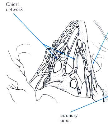
and are termed Chiari networks (figure 4.10h-1) Similar remnants
may be seen across the fossa ovalis.They are remnants of the
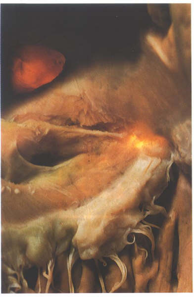
left sinus venosus valve (figure 4.10g-2).The atrial appendage
usually shows a considerable pouch at its junction with the
atrium anterior and inferior to the orifice of the inferior
vena cava, the so-called sub-eustachian sinus (figure4.10h-2).The
crista itself runs forwards onto the posterior margin of the
tricuspid orifice as a muscular sheet which inserts into the
inferior and septal leaflets of the tricuspid valve(4.10h-2).
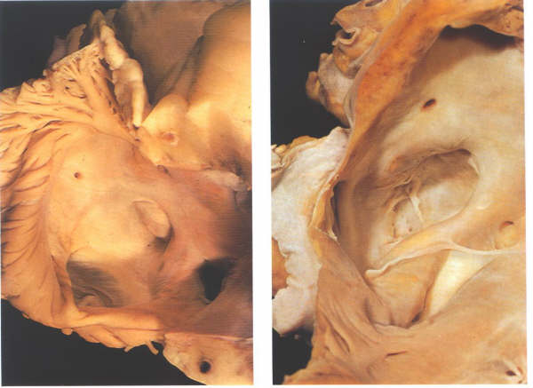
Figure 4.10g
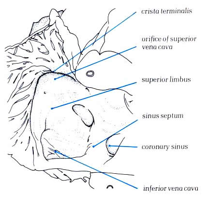
Diagram -
Figure 4.10g-1:
Dissection showing how the superior inferior vena cava
enters the right atrium between the crista terminalis and the
superior limbus of the fossa ovalis.
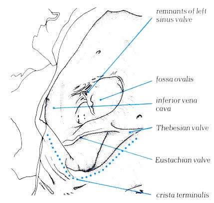
Diagram
- Figure 4.10g-2:
Dissection of the lateral wall
of right atrium showing the relationship of the crista terminalis
to the inferior vena cav, the fossa ovalis and the coronary
sinus.
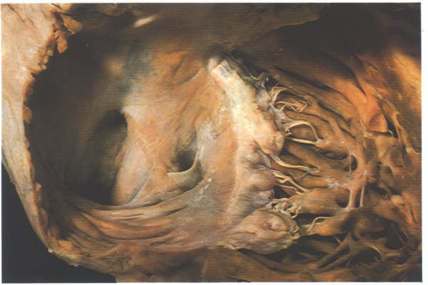
Fig.4.10h-1:
Remnants of the extensive right valve of the sinus venosus termed
the Chiari network.
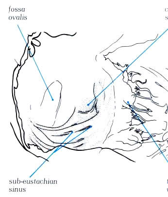
Diagram -
Figure 4.10h-1
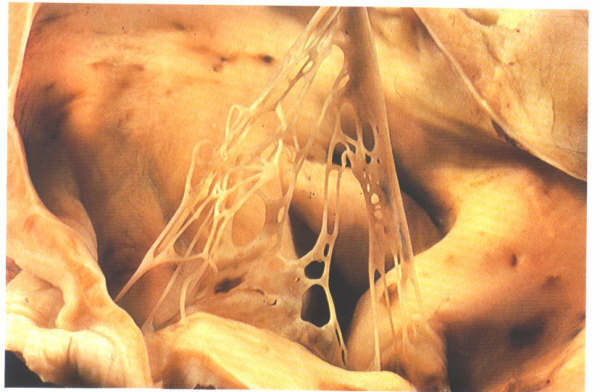
Fig.4.10h-1a:
Opened right atrium showing the extensive trabecular pouch found
beneath the orifice of the inferior vena cava(the so-called
sub-eustachian sinus).
Schematic - Figure
4.10h-1a
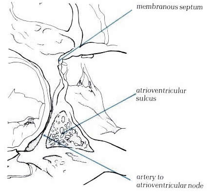
Figure
4.10i-1: Dissection of the sinus septum showing the tendon
of Todaro. The heart has been transilluminated from the left
ventricle to show the position of the membranous septum.
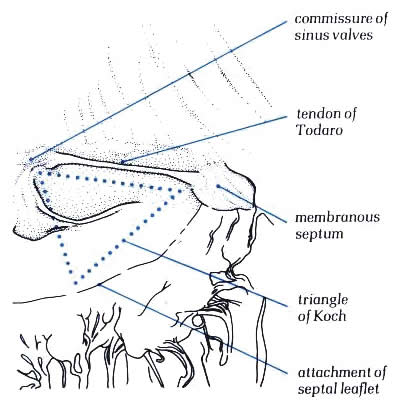
Diagram - Figure
4.10i-1.
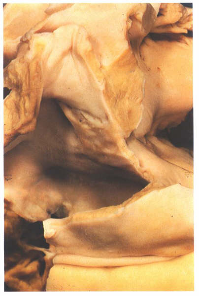
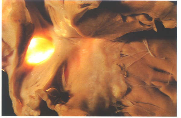
Figure 4.10i-2:
Dissection of the atrial
septum from behind showing the limbus of the fossa ovalis is
an infolding of the atrial roof and showing the position of
the flap valve.
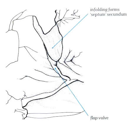
Diagram - Figure
4.10i-2
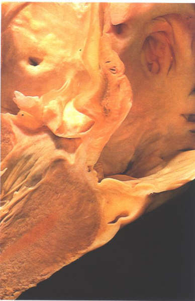
The posteroseptal surface of the right atrium
is, at first sight, extensive and is characterized by the orifice
of the coronary sinus, the third of the systemic venous channels
which drain into to the right atrium (4.10i-1 and 4.10i-2).The
fossa ovalis is the depression at the site of the fetal interatrial
communication termed the foramen ovale. In fetal life, this
hole permits richly oxgenated blood (coming from the placenta)
to reacch the left atrium and has a well-marked rim or limbus.Superiorly,
the limbus forms the 'septum secundum' between the superior
vena cava and the pulmonary veins(fig.4.10g-2). Anteriorly,
the limbus is the interatrial groove running behind the
aorta. Inferiorly, the limbus overlies the central fibrous body
and continues backwards as the structure separating the orifice of
the coronary sinus from that of the inferior vena cava.
this structure is termed the the sinus septum (fig.4.10g-2)
the degree of accentuation of the limbic structure(compare figs.4.10g-1
and 4.10g--2) depends on the amount of fat in the interatrial
groove. A tendinous structure extends through the sinus septum
in most hearts, being a continuation of the commissure between
the Eustachian and Thesebian valves. It runs intramyocardially
to insert into the central fibrous body but can be easily demonstrated
by superficial dissection(4.10i-1). It is termed the tendon
of Todaro and is a vital structure in demarcating the
position of the atrioventricular node.The posterior limbus of
the fossa ovale is very variable in its formation. In some hearts,
a well formed posterior lip is seen (fig.4.10e-2); In others,
the posterior wall of the fossa is directly continuous with
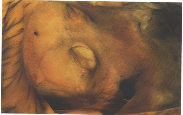
the left wall of the inferior vena cava ( fig.4.10g-2).The floor
of fossa ovalis is a thin fibromuscular partition-the flap valve
( fig.4.10i-3,4).It can be easily transilluminated (fig.4.10j-1
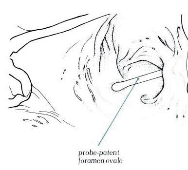
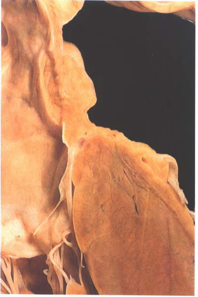
and fig.4.10j-2). In normal hearts, the flap valve is of sufficiently
large size to close completely the fossa ovalis. However, it
is not always adherent at its superior margin, and in approximately
25% of the normal hearts, a probe can be passed through
this site from right to left atrium producing a so-called
probe-patent foramen ovale (fig.4.10k-1 and fig.4.10k-2).
However, because of this valve-like
architecture, such a probe-patetnt foramen ovale does not permint
an interatrial shunt as long as the left atrial pressure is
higher than that of the right atrium.
The size of the opening of the coronary sinus
is variable, but it is always placed between the sinus septum
and the extension of the crista terminalis (figs.4.10l and 4.10l-1).
An extensive band of atrial muscle is present inferior to the
orifice which extends into the leaflets of the tricuspid valve.
Although this is the wall of the right atrium, it also overlies
the ventricular musculature due to the low attachment of the
tricuspid leaflets. The area is not part of the atrial septum.
Anteriorly, this muscle band merges with the
anterior limbus and sinus septum, forming the atrioventricular
node. Frequently, small openings are present in this sheet from
which venous channels extend into the conduction
tissues of the atrioventricular junctional area. These, together
with the tendon of Todaro, form better markers of the site of
the atrioventricular node than the opening of the coronary sinus.
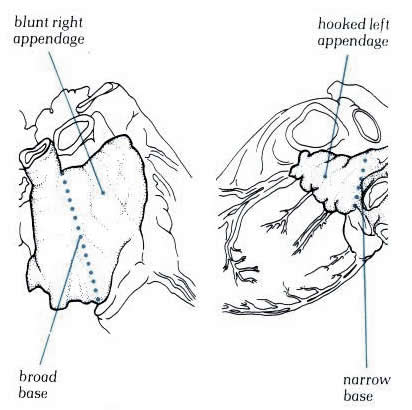
The anterior wall of the right atrium is the atrial appendage.
Seen externally, it has a characteristic blunt shape which serves
to distinguish it from the left atrial appendage ( figs. 4.10m
and 4.10m-1). Internally, the appendage, is lined by multiple
trabeculae which extend at right aangles to the crista terminalis
all along its length, continuing inferiorly into the subeustachian
sinus (Figs. 4.10k, 4.10h, 4.10e). In the roof of the atrium,
one of the trabeculae is frequently prominent and is sometimes
termed the septum spurium.
Figure
4.10j-1: Transillumination
fo the atrial septum showing the position of the fossa
ovalis
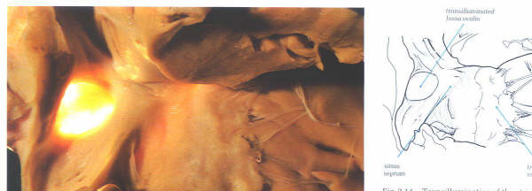
Figure 4.10j-2:
Figure 4.10j-1: and
Schematic of Fig.4.10j-1
Figure
4.10k-1: The heart with a probe-patent foramenn
ovale. The probe has been passed through th gap between
th eflap valve and the superior limbus
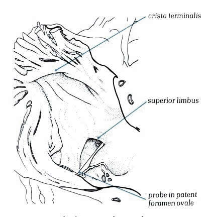
Diagram - Figure
4.10k-2
Figure
4.10l: The septal surface of the right atrium showing
the relationsip of the fossa ovalis to the ostium of the coronary
sinus.
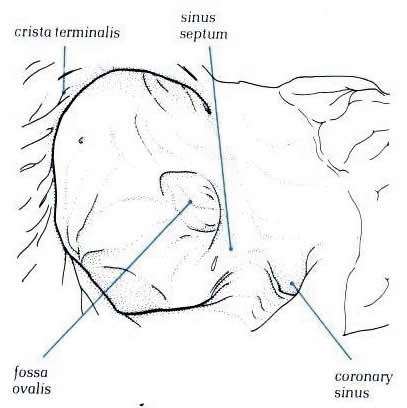
Diagram - Figure
4.10l-1
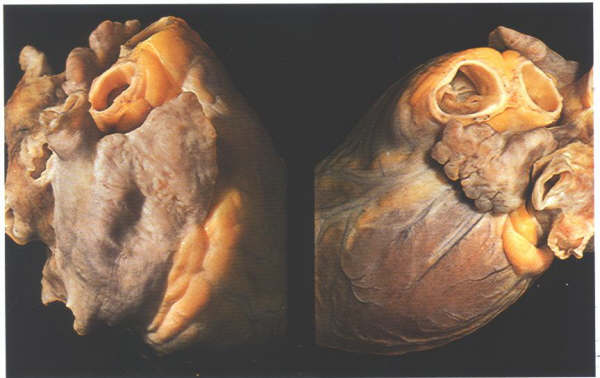
Figure
4.10m: The differing morphology of the right and left
atrial appendages.
Schematic
- Figure 4.10m-1
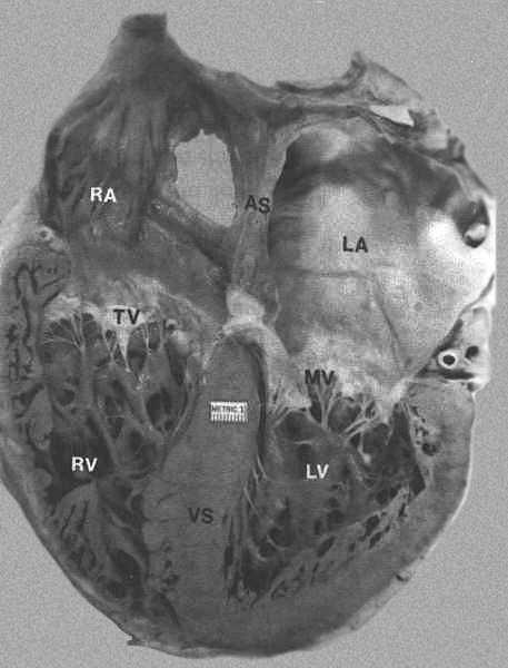
FIGURE 8
- Four-chamber view of the heart showing morphologic differences
between the four chambers. The right atrium (RA) is more trabeculated
than the left (LA), and the right ventricle is more heavily
and coarsely trabeculated compared to the left ventricle (LV).
AS = atrial septum; MV = mitral valve; TV = tricuspid valve;
VS = ventricular septum. From Hurst’s
THE Heart, Eighth edition, page 66) .
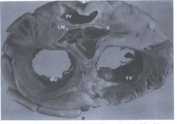
FIGURE 5 -
Cross-sectional view of heart showing aortic valve (AV), pulmonary
trunk (PT), origin of the right (R) and left main (LM), coronary
arteries, tricuspid (TV) and mitral(MV) valves, and atrial septum(AS).
A = anterior; P = posterior. (From
Hurst’s THE Heart, Eighth edition, page 63.)
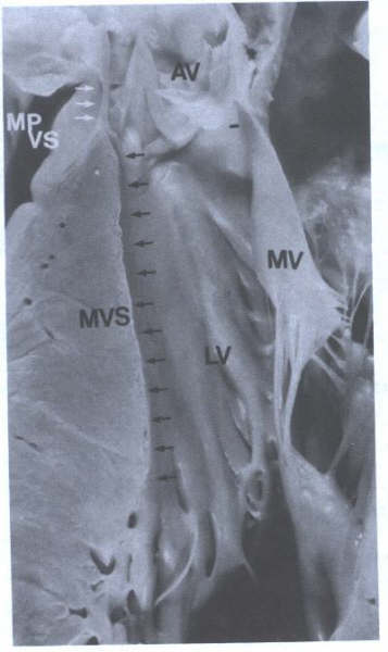
FIGURE 5A - Specimen
showing the muscular ventricular septum (MVS)(black arrows)
and membranous portion of the ventricular septum(MPVS)(white
arrows).LV = left ventricle; MV = mitral valve.
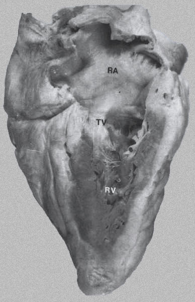
FIGURE 6 - Long-axis
view of the right side of heart right ventricle (RV), right
atrium (RA), and tricuspid valve (TV). The RV walls are heavily
trabeculated. (From Hurst’s THE
Heart, Eighth edition, page 64).
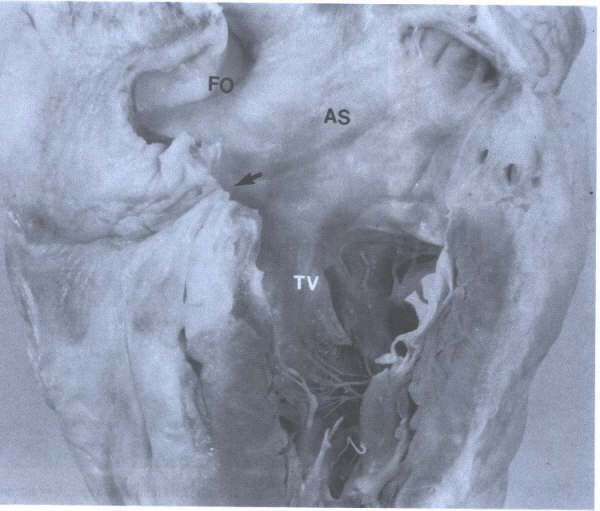
FIGURE 7 - Closeup
of right atrium showing atrial septum (AS), foramen ovale (FO),
entrance to orifice of coronary sinus (arrow), and tricuspid
valve (TV). From Hurst’s THE Heart,
Eighth edition, page 65.
The inner surface of the posterior and medial
(septal) walls of the right atrium is smooth, while the surfaces
of the lateral wall and of the right atrial appendage are composed
of parallel muscle bundles, the pectinate muscles (Figs. 4 and
7). The right atrial wall measures almost 2 mm in thickness.
The superior and inferior venae cavae enter the right atrium
posteriorly and medially at its superior and inferior aspects.
The orifice of the superior vena cava usually has no valve;
the orifice of the inferior vena cava is flanked anteriorly
by an inconstant, rudimentary valve, the eustachian valve, formed
by a crescentic fold. The caval orifices may vary in shape and
diameter depending upon the phase of respiration, the cardiac
cycle, and the contraction or relaxation of surrounding muscular
hands. The variation in the orifice may play some role in promoting
venous return or preventing atrial reflux. The medial wall of
the right atrium includes the atrial septum and is also important
because of its proximity to several structures (Figs. 5 and
6 to 7). Anteriorly, the posterior (noncoronary) cusp and the
right coronary cusp of the aortic root lean against the medial
right atrium, forming a normal slight bulge known as the torus
aorticus, which is a useful landmark during transseptal catheterization
of the left side of the heart. The proximal right coronary artery
is in the immediate vicinity as it enters the coronary sulcus.
The proximity of the aortic root to the right atrium permits
an aneurysm of the sinus of Valsalva to rupture into the right
atrium.
The atrial septum (Figs.1C, 3, 4, 5, and 6
to 7) is found in the posteroinferior portion of the medial
wall of the right atrium and extends obliquely forward from
right to left. Near the center of the atrial septum there is
a shallow depression, the fossa ovalis, which often has a prominent
fold, or limbus, anteriorly. The ostium of the coronary sinus
is located between the inferior vena cava and the tricuspid
valve (Figs. 4, 6 to 7). The orifice of the coronary sinus is
guarded by a rudimentary flap of tissue, the Thebesian valve.
The AV node is located in the lower atrial septum, anterior
and medial to the coronary sinus, just above the septal leaflet
of the tricuspid valve. The sinus and AV nodes, as well as the
entire conducting pathways, are not grossly visible.
Right Ventricle
INTRODUCTION
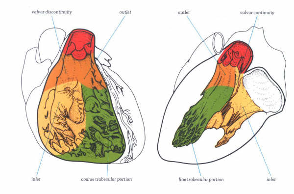
Figure 1D:
Diagrammatic representation of the three basic components of
the right and left ventricles. Each has an inlet component containing
atrioventricular valve; an apical trabecular zone; and an outlet
component supporting an arterial valve.
Each ventricle has basically the same pattern,
composed of an inlet atrioventricular valve and its tension
apparatus, a body and an outlet arterial valve. As with the
atria, there are important morphological differences between
the ventricles which permit their clinical distinction. Therefore,
each ventricle is described concentrating upon its inlet and
outlet valves, and then follows a description of the interventricular
septum. The ventricles are described in terms of three parts
: an inlet, containing an atrioventricular valve and its tension
apparatus; a trabecular body; and a outlet supporting an arterial
valve. In similar fashion, the muscular ventricular septum is
described as composed of inlet (separating the atrioventricular
valves) ; trabecular (between the trabecular zones)
; and outlet (between the arterial valves) portions.
This division is not meant to indicate that ventricular inlet
and outlet portions lack trabeculations, although in many places
they do have smooth walls. Rather it indicates that the apical
trabecular zones are the most trabeculated and most distinctive
atrioventricular valves is similar in each ventricle (figs.
1D-1 & 1D-2) although distinctive differences exist and
will be described in the sections devoted to the tricuspid and
mitral valves. Basically, each valve is made up of a number
of leaflets consisting of a fibrous tissue core, the maior support
of this being the atrioventricular annulus. The core is termed
the fibrosa and is continuous distally with the chordae tendineae.
The chordae tendineae, composed of dense collagen, are in turn
attached to the ventricular myocardium, most coming from specialized
papillary muscles but some chordae taking origin from the ventricular
walls The chordae and papillary muscles make up the valvar tension
apparatus.
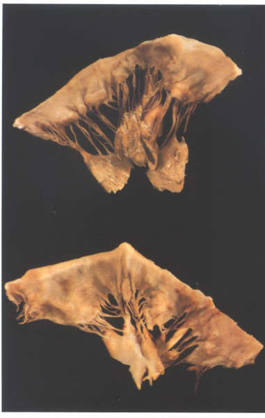
Figure1D-1:
The removed mitral (upper) and
tricuspid (lower) valves viewed from their atrial aspect.
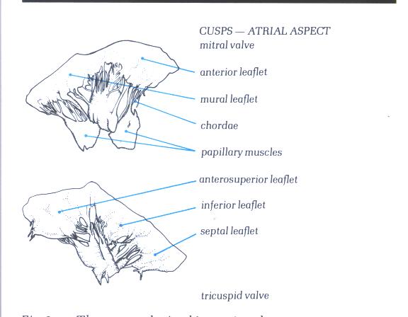
Figure1D-1a:
Drawing and labelling of Figure1D-1.
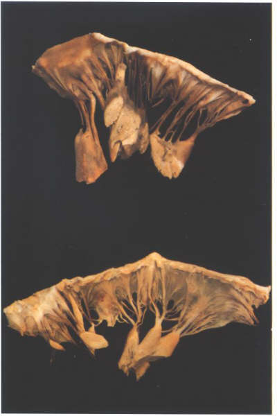
Figure1D-2:
The removed mitral (upper) and tricuspid
(lower) valves viewed from their ventricular aspect.
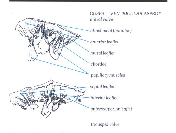
Figure 1D-2a : Drawing
and labelling of Figure 1D-2.
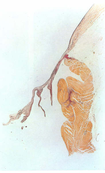
Figure1D-3:
Histology
of an atrioventricular valve.
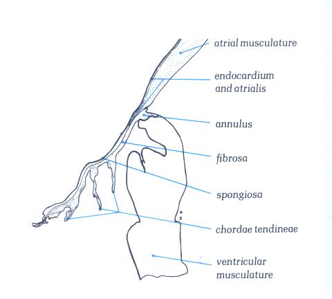
Figure 1D-3a: Labelling
of structures in Figure 1D-3
The fibrosa forms the ventricular layer of
the valve; on its atrial surface which is continuous with the
atrial endocardium and which is separated from the fibrosa by
a more loosely textured layer of fibrous tissue termed the spongiosa
(fig. 1D-3). The distal end of the atrial myocardiukm may also
extend for a distance between the atrialis and the fibrosa.
Apart from the blood vessels present in the atrial musculature,
the valve leaflets and chordae are avascular structures.
The major chordae supporting a leaflet insert
either into its free edge, or the area beyond the free edge
on the ventricular aspect up to the line of closure of the leaflet.
This area between the free edge and the line of closure is termed
the rough zone in contradistinction to the area between the
line of closure and the basal attachment of the leaflet which
is easily transilluminated and is smooth (figs.1- D4 and 1-D4a).
It is important to remember that the line of closure of a leaflet
is not its free edge(Fig.1-D5 and 1-D5a).
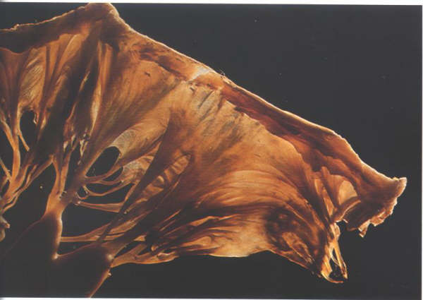
Figure1-D4:
Transillumination mitral valve
showing the rough zone from the free edge to the line of closure
of the valve and the clear azone between the line of closure
and the annulus.
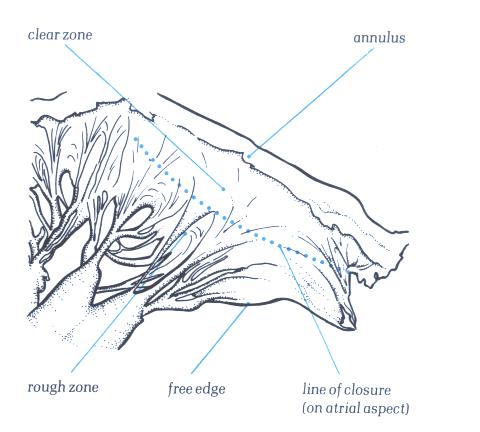
Figure 1-D4a:
Labelling of structures in fig.1-D4.
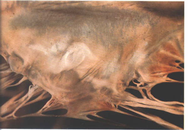
Figure 1-D5:
The atrial surface of the mitral
valve showing how the line of closure is some distance from
the free edge of the valve.
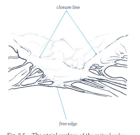
Figure 1-D5a:
Labelling of structures in fig.1-D5.
The chordae inserting into the rough zone
are called rough zone chordae (fig.1-D6). They are distinguished
from basal chordae which pass from the ventricular myocardium
to the ventricular aspect of the leaflet close to its attachment
(fig.1-D7) and commissural chordae which are the discrete fan-shaped
chordae inserting into the free margin of the leaflet only and
supporting two adjacent leaflets (figs.1-D8 & 1-D9). The
artioventricular valves are, therefore, intricate and complicated
structures, having several components. Each of these components
must function correctly and in a cooridinated fashion if the
valve itself is to be competent. From a functional standpoint,
the atrioventricular valves should not be considered solely
in terms of the leaflets and chordae. For this reason, the term
atrioventricular valve apparatus’ is more apt.
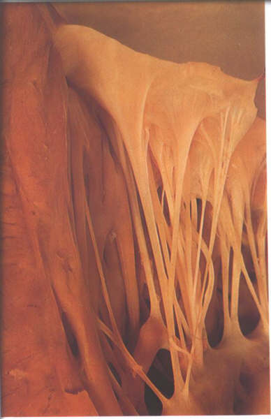
Figure 1-D6:
The ventricular aspect of the
mitral valve showing the attachment of rough zone chordae.

Figure 1-D6a:
Labelling of Fig.1-D6.
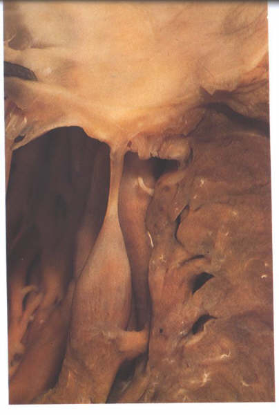
Figure 1-D7:
Dissection of the mitral valve showing the morphology of a basal
chorda.
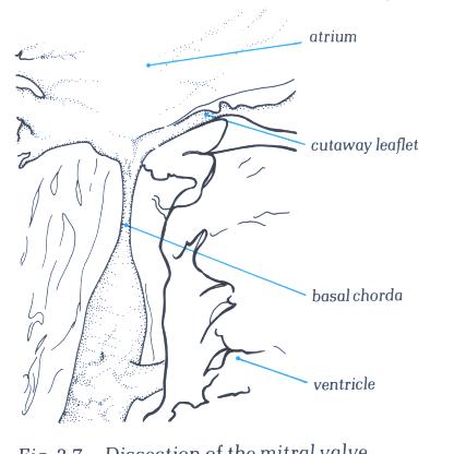
Figure 1-D7a: Labelling
of fig.1-D7a.
Figure 1-D8:
Commissural chordae of the mitral
valve.
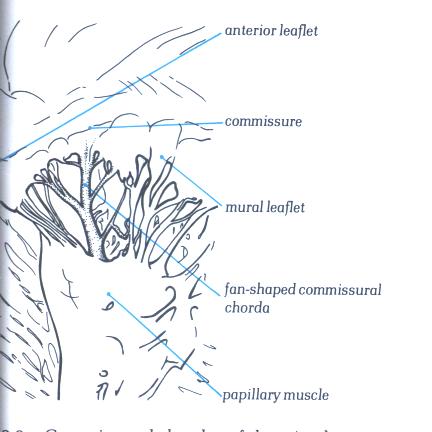
FIGURE 1-D8a:
Labelling of structures in figure
1-D8.
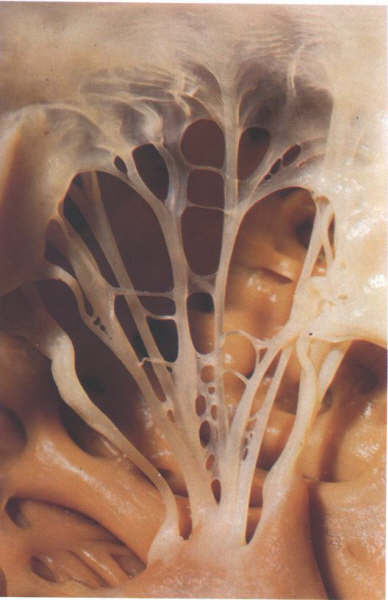
Figure 1-D9:
Commissural chordae of the tricuspid
valve.
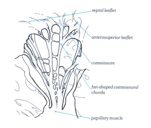
Figure 1-D9a:
Labelling of structures in figure
1-D9.
The right ventricle receives venous blood
from the right atrium during ventricular diastole and propels
blood into the pulmonary circulation during ventricular systole
(Figs.4, 6, 7, 8, 9 to 12). The right ventricle is normally
the most anterior cardiac chamber, lying directly beneath the
sternum (Figs.1 and 2). Enlargement or hyperactivity of the
right ventricle may often be detected by palpation of the sternum
or the lower left sternal border. The right ventricle is partially
below, in front of, and medial to the right atrium but anterior
and to the right of the left ventricle. Most of the entire inferior
border of the frontal roentgenogram view of the heart consists
of the right ventricle (Fig.1).
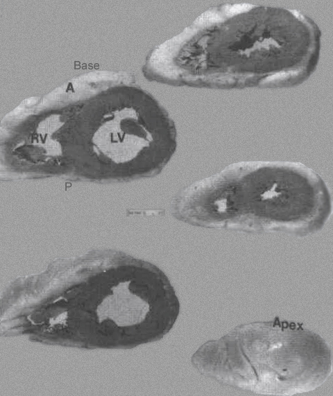
FIGURE 9 -
Family of ventricular slices from base to apex. A = anterior;
LV= left ventricle; right ventricle. P= posterior; VS = ventricular
septum. The LV cavity is more “circular” shaped compared to
the more “triangular” shaped RV cavity.
From Hurst’s THE Heart, Eighth edition, page 66.
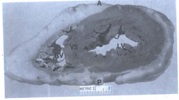
FIGURE 9A
- Closeup view of ventricular slice seen in FIG. 9. This view
corresponds to the short axis echocardiographic views of the
ventricular cavities. A = anterior; LV = left ventricle; RV
=right ventricle; VS = ventricular septum.
The striking difference in configuration between
the two ventricles is illustrated by a transverse section (See
above (Figs. 8, 9 and 10). The left ventricular chamber is an
ellipsoidal sphere surrounded by relatively thick (8 to 15 mm
at autopsy) musculature, well suited to ejecting blood against
the high resistance of the systemic vessels. The right ventricle,
which normally contracts against very low resistance, has a
crescent-shaped chamber and a thin outer wall, measuring 4 to
5 mm in thickness. The anterior right ventricular wall curves
over the ventricular septum, which normally bulges into the
right ventricular cavity. Although the ventricular septum forms
the medial wall of both ventricles, it seems to contribute predominantly
to left ventricle function in normal subjects. The anterior
and inferior walls of the right ventricular cavity are lined
by muscle bundles, the trabeculae carneae, which often form
ridges along the inner surface of the wall or cross from one
wall to the other (Figs. 6 to 8). A rather constant muscle,
the moderator band, crosses from the lower ventricular septum
to the anterior wall, where it joins the anterior papillary
muscle (Figs.4 to 7). The right bundle branch, after traveling
through the muscular ventricular septum, courses through the
moderator muscle to the endocardium of the right ventricle.
Functionally, the right ventricle can be partitioned
into an inflow tract, an outflow tract, and an apical trabecular
component (body). The trabecular muscles in the apex of the
right ventricle are much more coarse than those in the left
ventricle. The inflow tract, consisting of the tricuspid valve
and the trabecular muscles of the anterior and inferior walls,
directs entering blood anteriorly, inferiorly, and to the left
at an angle of 60° to the outflow tract (Fig. 6). The smooth-walled
outflow tract, also referred to as the infundibulum, forms the
superior portion of the right ventricle. It is separated from
the inflow tract by a thick muscle, the crista supraventricularis,
which arches from the anterolateral wall over the anterior leaflet
of the tricuspid valve to the septal (medial) wall, where it
joins other constrictor bands of muscle that encircle the outflow
tract (Figs. 6 and 10). Blood entering the infundibulum is ejected
superiorly and posteriorly into the pulmonary trunk.
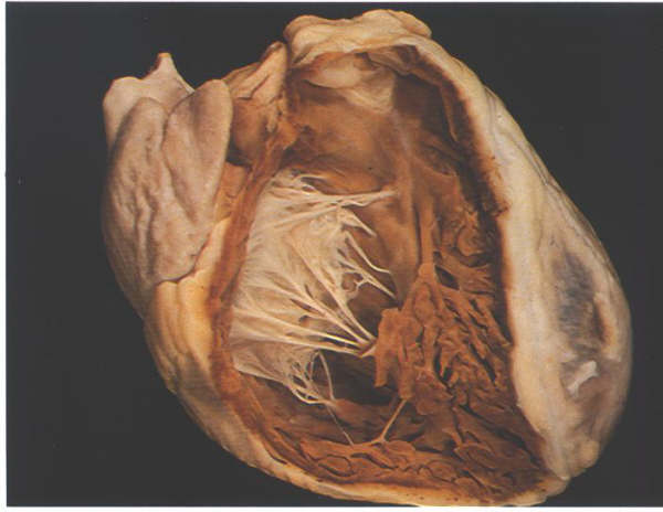
FIGURE 6A: The
heart positioned in its situ position with the anterior wall
removed to show the extent of the morpholobgically right ventricle.
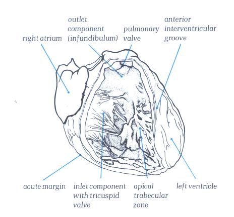
FIGURE 6A-1: Labelling
of structures in Figure 6A above.
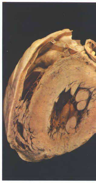
FIGURE 6B: Short
axis section through the ventricular mass showing how the right
ventricle wraps around the left ventricle.
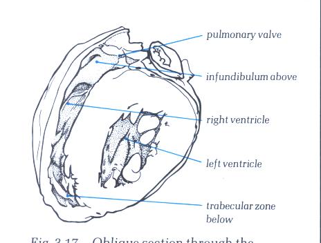
FIGURE 6B-1: Labelling
of structures in Figure 6B above.
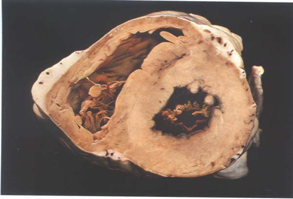
FIGURE 6C: Short
axis section through the ventricular mass showing how the right
ventricle wraps itself around the left ventricle.
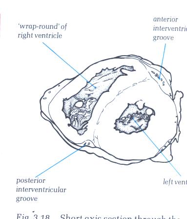
FIGURE 6C-1: Labelling
of structures in Figure 6C above.
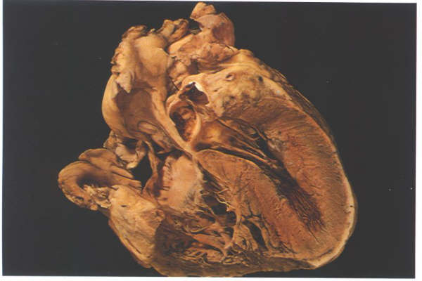
FIGURE 6D: Frontal
section through the heart showing the junction between the inlet
and trabecular portions of the right ventricle, with the inlet
septum extending to the position of the crux (posterior junction
of the arterial and ventricular septa).
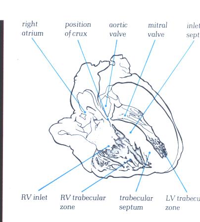
FIGURE 6D-1: Labelling
of structures in Figure 6D above.
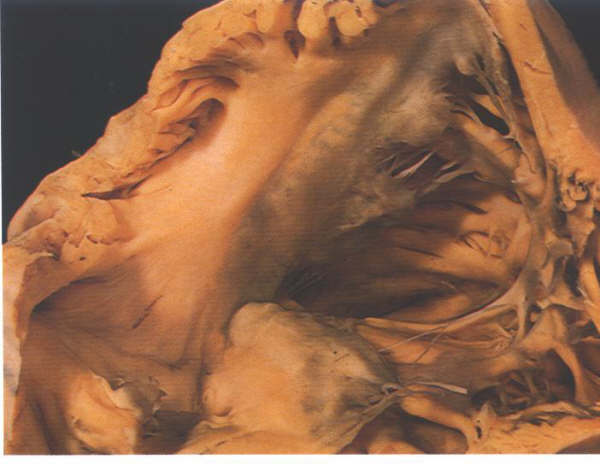
FIGURE 6E: The
inlet componen of the right ventricle viewed from behind showing
the transition into the trabecular zone. Note also the leaflets
of the valve separated by the commoissures.
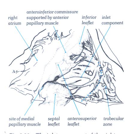
FIGURE 6E-1: Labelling
of structures in figure 6E.
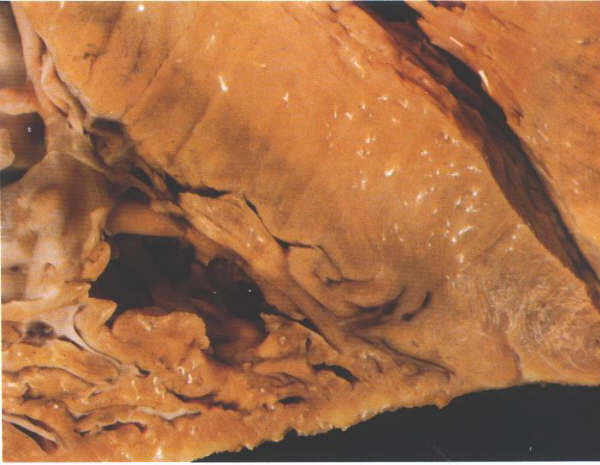
FIGURE 6F: Section
through the ventricular apex showing how thin both the right
and the left ventricular myocardia are at this point.
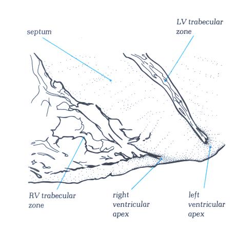
FIGURE 6F-1: Labelling
of structures in figure 6F.
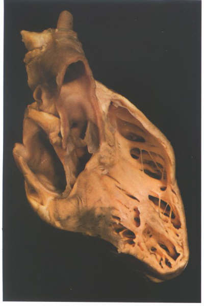
FIGURE 6G: The
ventricular mass of the heart viewed from its right side after
removal of the inlet and part of the outlet components of the
right ventricle. It shows how the trabecular zone is suspended
like a piece of washing from the washing line made up of the
inlet and outlet components.

FIGURE 6G-1: Labelling
of structures in figure 6G.
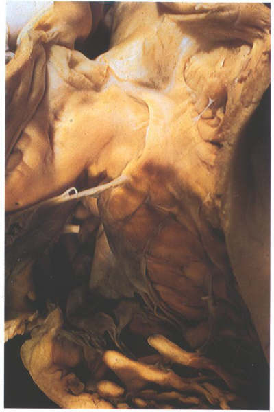
FIGURE 6H: The
right ventricle viewed from the front showing the structure
of the infundibulum, a muscular tube which supports the pulmonary
valve.
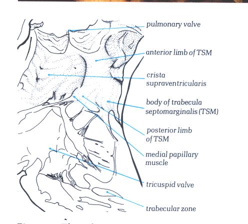
FIGURE 6H-1: Labelling
of structures in figure 6H.
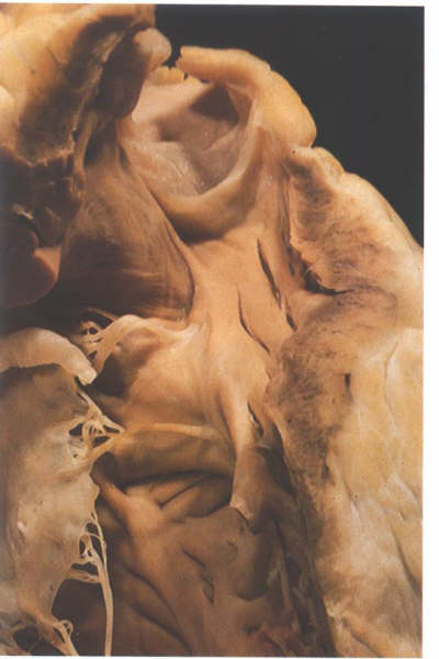
FIGURE 6-I: Dissection
of the outflow part of the right ventricle showing the difference
between the crista supraventricularis (the supraventricular
crest separating the tricuspid from the pulmonary valve) and
the trabecular septomarginalis (TSM) which is an extensive septal
trabeculation. Note the distinct raphe between the two structrures.
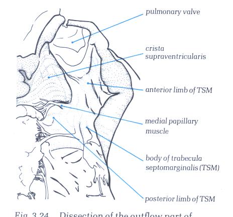
FIGURE 6I-1: Labelling
of the structures in figure 6-I above.
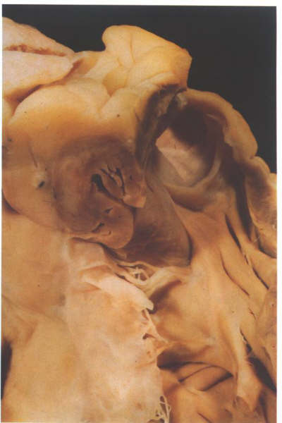
FIGURE 6J: Further
dissection of the heart shown in figure 6-I above demonstrates
that most of the crista supraventricularis is made up of the
heart wall rather than septal structures. Note its relationshipp
to the epicardial fat and the coronary artery.
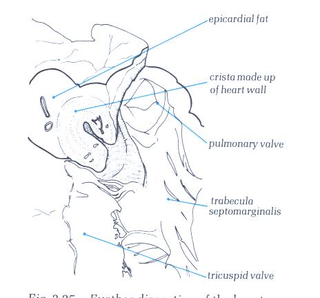
FIGURE 6J-1: Labelling
of the structures in figure 6-J above.
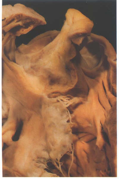
FIGURE 6K: Still
further dissection confirms that the crista is made up in its
larger part of the outer heart wall.
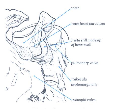
FIGURE 6K-1: Labelling
of structures in Figure 6K above.
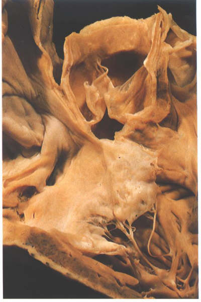
FIGURE 6L: Sectioning
into the aorta in this heart shows that only the extreme septal
insertion of the crista supraventricularis is made up of infundibular
septum.
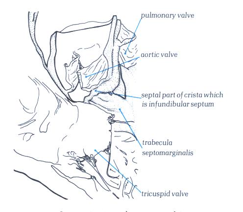
FIGURE 6L-1: Labelling
of structures in Figure 6L above.
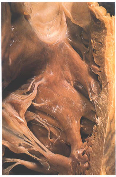
FIGURE 6M: The
septal surface of the right ventricle. The raphe between trabecula
septomarginalis and crista is less well seen in this heart than
in the heart shown in figure 6-I.
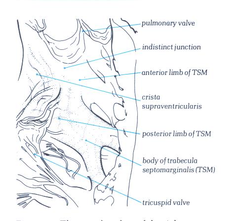
FIGURE 6M-1: Labelling
of structures in figure 6M.
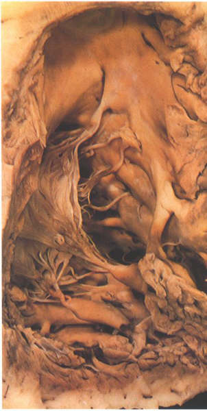
FIGURE 6N: The
moderator band of the right ventricle. It is an extension from
the apex of the trabecula septomarginalis.
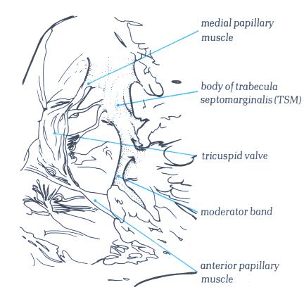
FIGURE 6N-1: Labelling
of structures in figure 6N.
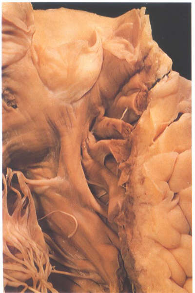
FIGURE 6O: The
multiple muscular bars which line the anterior aspect of the
infundibulum of the right ventricle.
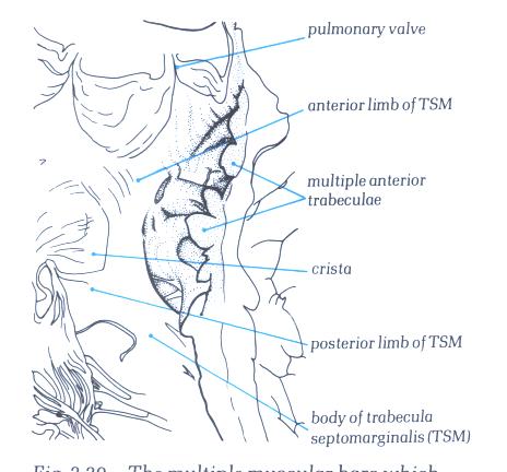
FIGURE 6O-1: Labelling
of structures in figure 6-O.
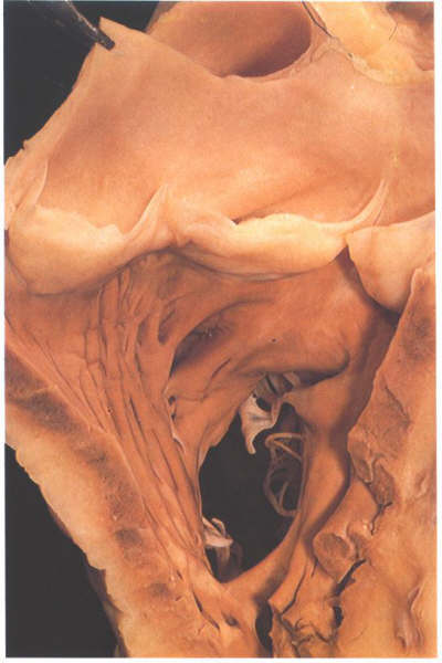
FIGURE 6P: The
infundibulum of the right ventricle viewed from the front showing
the muscular annulus formed by the crista supraventricularis
and its parietal extension and the trabecula septomarginalis
together with the moderator band.
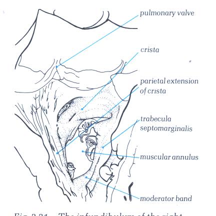
FIGURE 6P-1: Labelling
of structures in figure 6P.
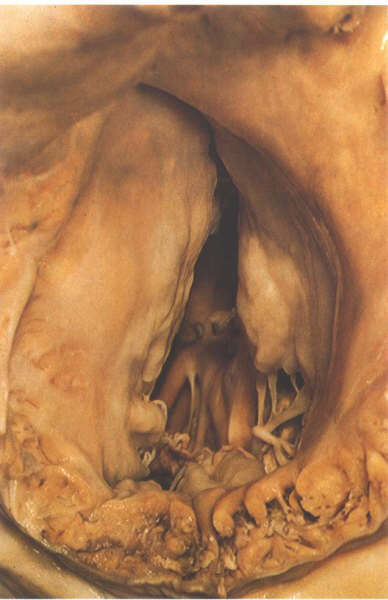
FIGURE 6Q: The
tricuspid valve viewed from behind with the heart in its in
situ position.The three leaflets occupy septal, anterosuperior
and inferior positions.
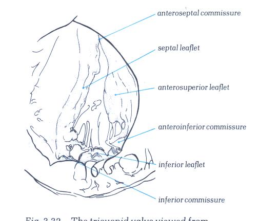
FIGURE 6Q-1: Labelling
of structures in figure 6Q.
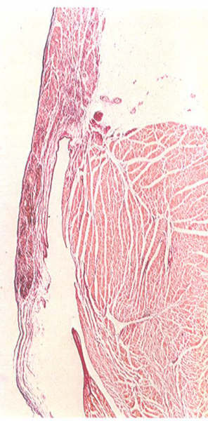
FIGURE 6R: Histology
of the tricuspid ring. The leaflet does not spring from a strong
well-formed annulus as in the mitral valve.
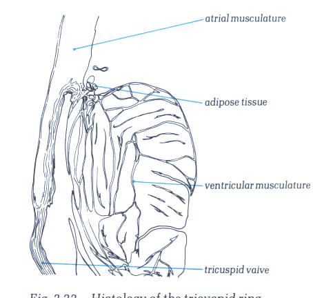
FIGURE 6R-1: Labelling
of structures in figure 6R.
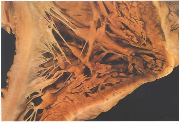
FIGURE 6S: The
inlet part of the right ventricle showing the multiple papillary
muscles supporting the septal and inferior leaflets. However,
only one, the posterior papillary muscle, gives rise to a commissural
chord.
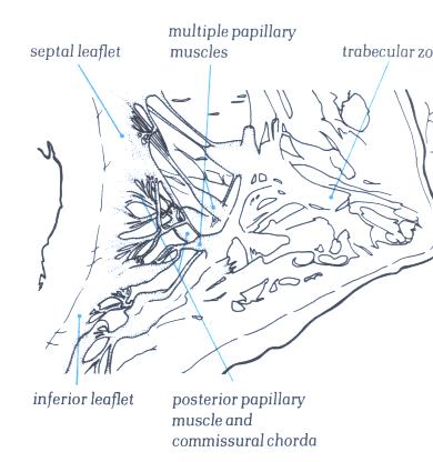
FIGURE 6S-1: Labelling
of structures in figure 6S.
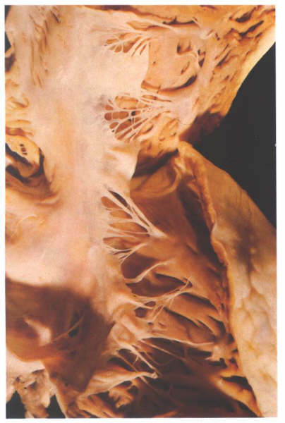
FIGURE 6T: The
anteroseptal commissure of the tricuspid valve viewed from behind
having opened the valve through the inferior commissure is supported
by the medial commissure. Note that the anteroseptal papillary
muscle is superior to and to the right of the membranous septum.
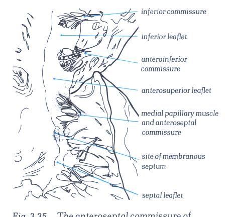
FIGURE 6T-1: Labelling
of structures in figure 6T.
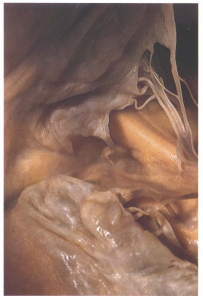
FIGURE 6U: A
heart with a cleft in the septal leaflet of the tricuspid valve
at the site of the menbranous septum.
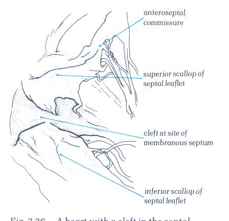
FIGURE 6U-1: Labelling
of the structures in figure 6U.
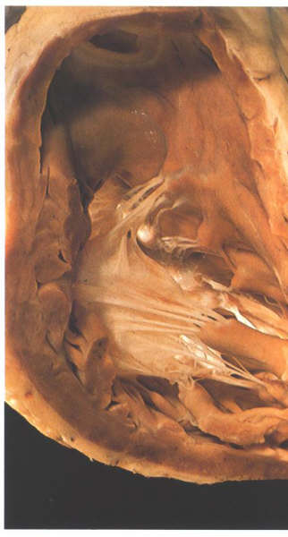
FIGURE 6V: A
frequent variant in tricuspid valve morphology is for the large
anterior papillary muscle to support the midzone of the anterosuperior
leaflet. The anteroinferior commissure in this heart is supported
by an accessory anterior papillary muscle.
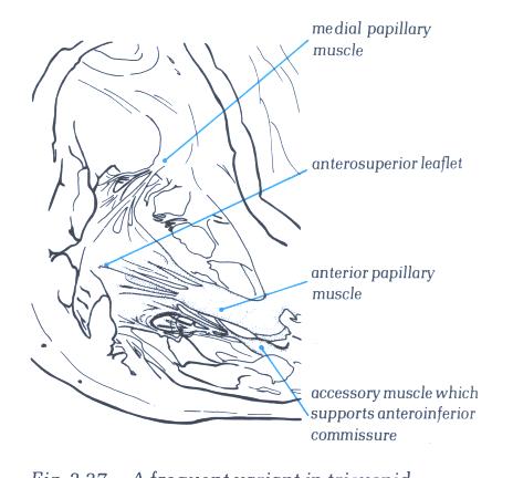
FIGURE 6V-1: Labelling
of the structures in figure 6V.
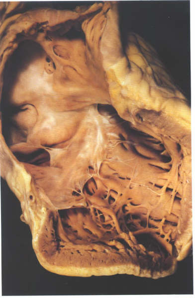
FIGURE 6W: The
opened inlet portion of the right ventricle showing the inferior
commissure. Note that the other small muscles do not give rise
to commissural chordae.
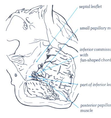
FIGURE 6W-1: Labelling
of structures in figure 6W.
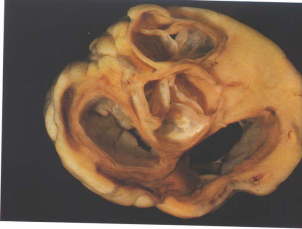
FIGURE 6X: The
atrioventricular junction viewed from its atrial aspect after
removal of the atrial chambers and the great arteries. It shows
the relationships of the leaflets of pulmonary and aortic valves.
The two leaflets of these valves always face each other, permitting
the nomination of the right-facing and left-facing leaflets
of the pulmonary valves.
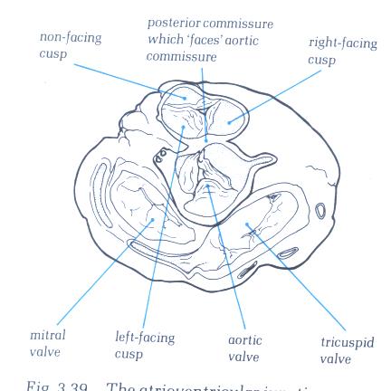
FIGURE 6X-1: Labelling
of the structures in figure 6X.
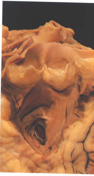
FIGURE 6Y: The
infundibulum of the right ventricle opened from the front showing
the morphology of the pulmonary valve.
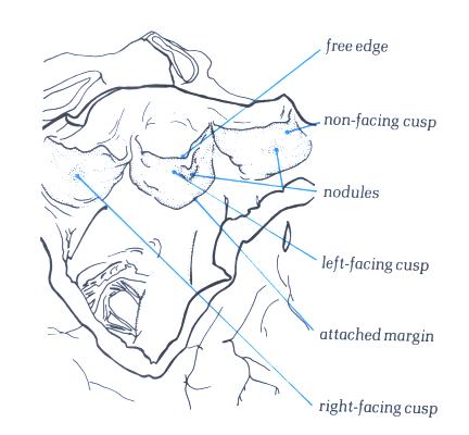
FIGURE 6Y-1: Labelling
of the structures in figure 6Y.
The Morphologically Left Ventricle
The left ventricle is a conical structure
with tubular walls which narrow down to a rounded apex. It comprises
an inlet portion, containing the mitral valve and its tension
apparatus; an apical rabecular zone characterized by fine trabeculations
and an outlet zone, supporting the aortic valve, which is incomplete
posteriorly so that the aortic and mitral valves are in fibrous
continuity.The left ventricle forms the greater part of diaphragmatic
surface of the heart but is overlaid anteriorly and superiorly
by the trabecular zone and outlet of the right ventricle . In
contrast to the right ventricle where there is a gentle curve
between inlet and outlet portions, the left ventricle shows
an acute angle between these portions, both extending down into
the trabecular zone separated by the anterior leaflet of the
mitral valve. Usually there is no structure comparable to the
crista supraventricularis in the left venricle owing to the
fibrous continuity of the inlet and outlet valves, although
in rare hearts, a muscular fold (ventriculo-infundibular fold)
may interpose between the valves. The septal surface of the
left ventricle is smooth, so that is no structure corresponding
to the trabecula septomarginalis in the left ventricle.
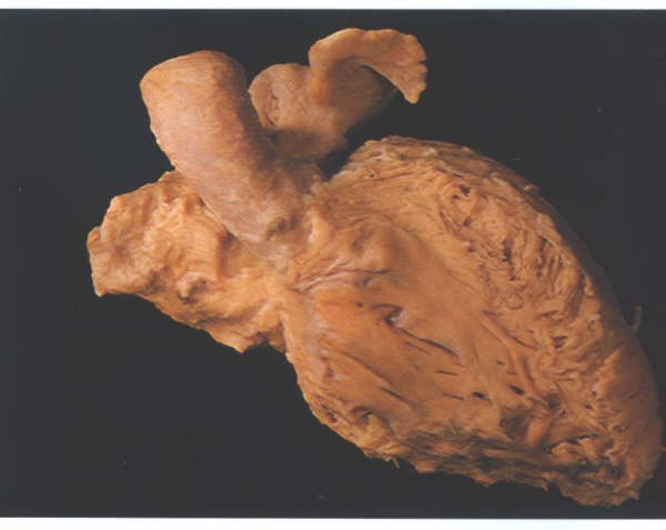
FIGURE 9B:
The left ventricle and atrium after removal of the right-sided
structures and viewed from the front.
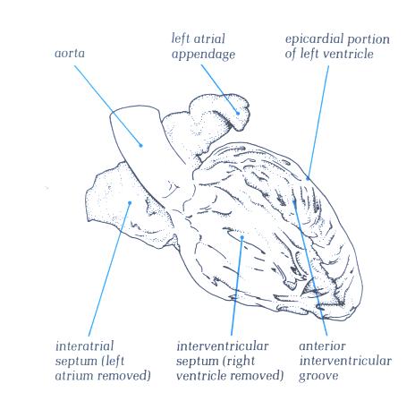
FIGURE 9B-1:
Labelling of structures in figure
9B.
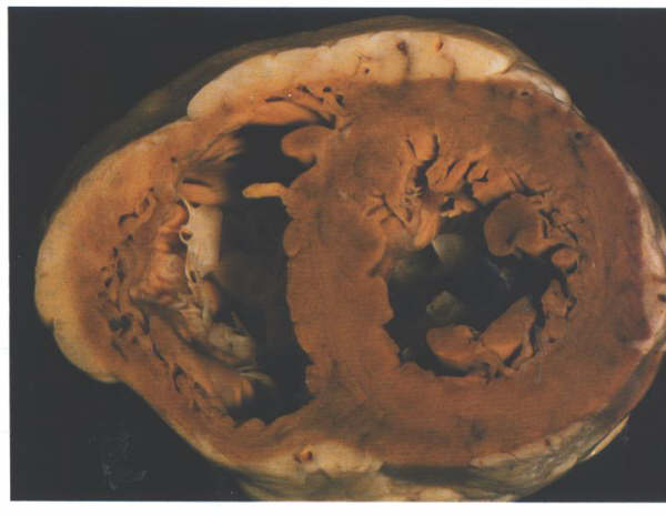
FIGURE 9C:
Short axis section of the ventricular
mass showing the tubular nature of the left ventricle.
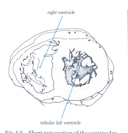
FIGURE 9C-1:
Labelling of structures in figure
9C.
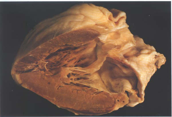
FIGURE 9D: The
opened left ventricle showing inlet,trabecular and outlet portions.
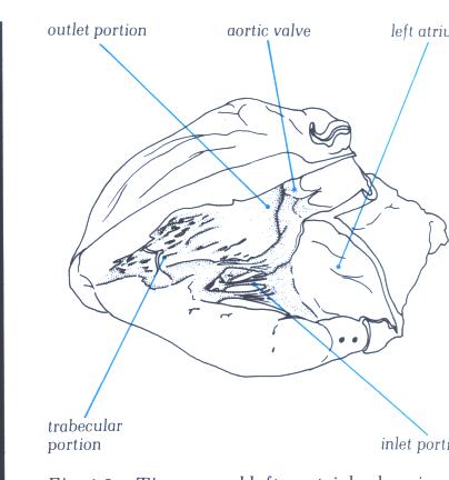
FIGURE 9D-1: Labelling
of structures in figure 9D.
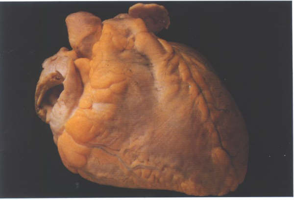
FIGURE 9E: A
heart viewed from the front.
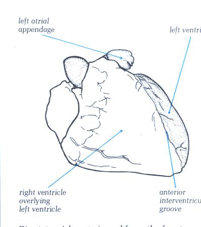
FIGURE 9E-1: Labelling
of structures in figure 9E.
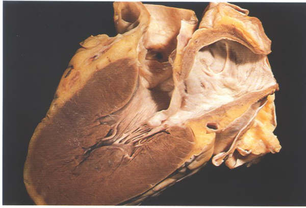
FIGURE 9F: Section
through the left ventricle showing how the anterior mitral valve
leaflet separates its inlet and outlet portions.
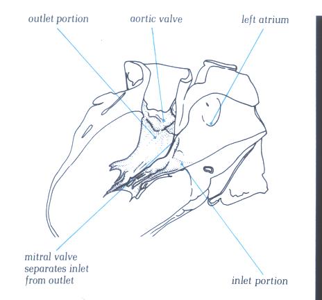
FIGURE 9F-1: Labelling
of figure 9F.
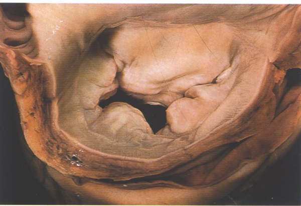
FIGURE 9G: Mitral
valve viewed from above showing the anterior or septal leaflet
and the posterior or mural leaflet with its three scallops.
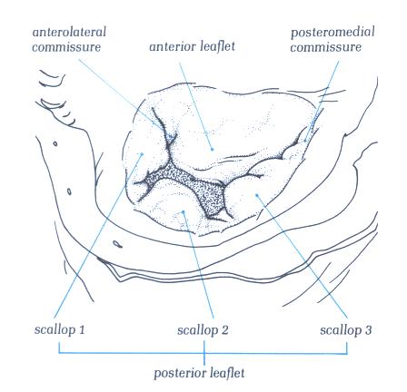
FIGURE 9G-1: Labelling
of figure 9G.
The Mitral Valve
The mitral valve is characteristically described
as having two leaflets, the anterior or septal and the posteror
or mural leaflets. The leaflets are separated by the posteromadial
and anterolateral commissures (fig.9G ). The anterior leaflet
is attached to less than half the circumference of the mitral
annulus but has considerable height and consequently presents
as a large leaflet (fig.9H).
The posterior leaflet, in contrast, is attached
to more than half the circumference (fig.G) but is less tall
(fig.H), and occupies only about the same area as the anterior
leaflet. Moreover, the posterior leaflet has a characteristic
scalloped contour. In the usual case three scallops can be distinguished
divided by clefts (fig.9G) These scallops are termed posteromedial,
middle and anterolateral. However, it is not at all unusual
to find aberrations from this pattern, two, four, five or more
scallops being seen in otherwise normal valves (fig.9I ).The
posterior leaflet throughout its length is attached to the mitral
atrioventricular annulus (fig.9J). The anterior leaflet, in
contrast, is in fibrous continuity with the aortic valve, the
two valves having a common annulus (fig.K) strengthened at each
end by the right and left fibrous trigones (fig.9L). The mitral
valve leaflets are supported by two papillary muscles groups
situated underneath the commissural areas in the posteromedial
and anterolateral positions (fig.9M). Their position is such
that the chordae between muscle and leaflet operate at the maximal
mechanical efficiency (fig.9N). Each papillary muscle supports
the adjacent part of both valve leaflets (fig.9N). There is
considerable variation in the morpholgy of the papillary muscles
themselves, particularly the posteromedial muscle. They may
be single pillar-like muscles or be composed of several heads
of differing size (compare figs.9P and 9Q). The different papillary
muscle architecture affects the chordal distribution (vide infra)
and also affects the mode of the arterial supply to the papillary
muscle complex. Because of the different topography of the anterior
and the posterior laeflets, there are corresponding differences
in the mode of chordal support, which also show considerable
individual variation. Thes variations may leave part of the
leaflet less well supported than would be antcipated.The anterior
leaflet is supported only by rough zone chordae together with
the commissural chords (fig.9P).The rough zone chords may be
strengthened by thicker tendinous structures, the so-called
strut chordae (fig.9R), usually one for each half of the leaflet.
The commissural chords spring from the tips of their papillary
muscle and fan out to attach to the free margins of both leaflets.
The posteromedial commissural chord usually fans out more than
that of the anterolateral commissure (compare figs. 9S and 9T).
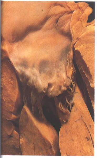
FIGURE 9H: The
anterior or septal leaflet of the mitral valve viewed from behind
after division of the valve through its commissure. The posterior
or mural leaflet is shown in Figure9C. Note that the anterior
leaflet is almost square.
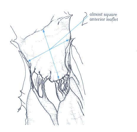
FIGURE 9H-1: Labelling
of figure 9H.
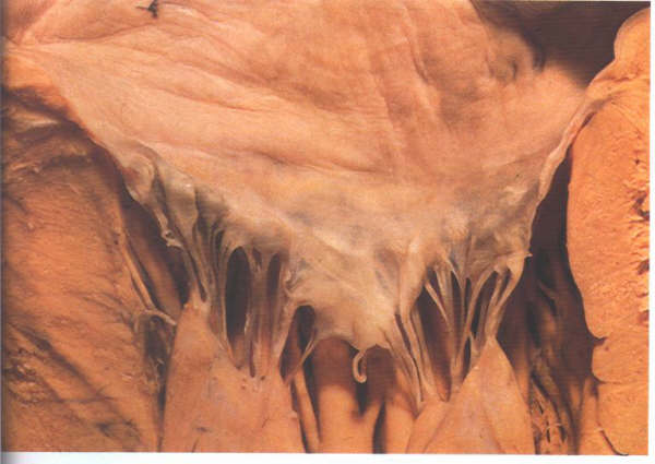
FIGURE 9I: The
posterior or mural leaflet of the divided mitral valve shown
in figure H viewed from the front. Note that the posterior leaflet
is long and narrow.
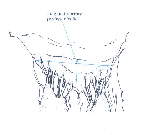
FIGURE 9I-1: Labelling
of figure 9I.
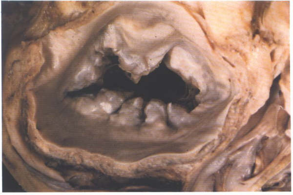
FIGURE 9J: Another
normal mitral valve viewed from above showing the variation
which exists in the number of scallops (compare with figure
9H).
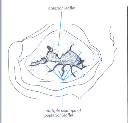
FIGURE 9J-1: Labelling
of structures in figure 9J.
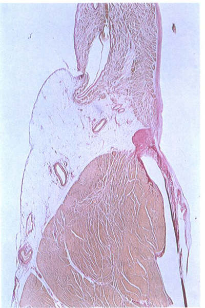
FIGURE 9K:
Histological section through the mitral ring. The leaflet takes
origin from a well-formed annulus (compare with figure 6S).
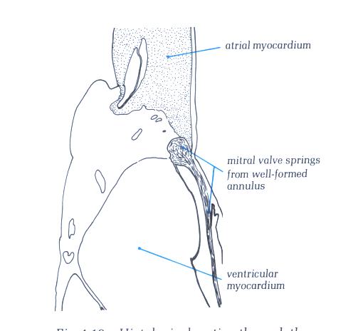
FIGURE 9K-1: Labelling
of structures in figure 9K.
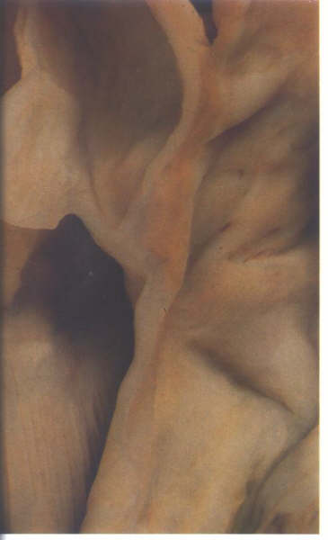
FIGURE 9L: Section
through the area of aortic-mitral fibrous continuity. The two
valves have a common annulus.
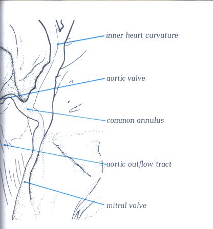
FIGURE 9L-1: Labelling
of structures in figure 9L.
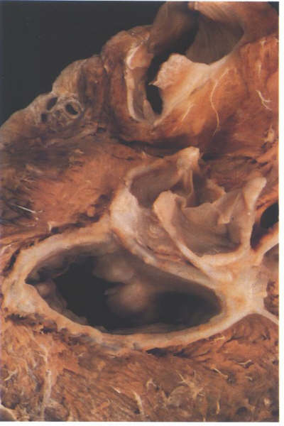
FIGURE 9M: Dissection
of the fibrous skeleton of the aortic and mitral valves viewed
from above and behind showing the thickening at either end of
the area of valve continuity.
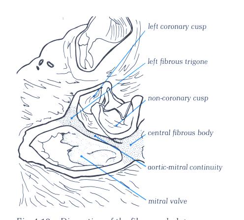
FIGURE 9M -1: Labelling
of structures in figure 9M.
FIGURE 9N: Cutaway
of the left ventricle showing the papillary muscle groups of
the mitral valve. Note how they arise adjacent to each other
when in their in situ position (compare with figure 9P).
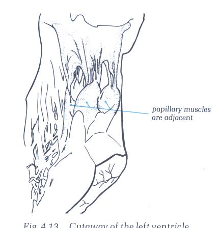
FIGURE 9N -1: Labelling
of structures in figure 9N.
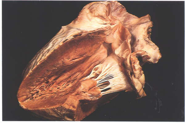
FIGURE 9O: Overall
view of the mitral unit showing how the muscles act at maximum
mechanical efficiency.
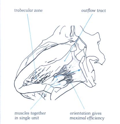
FIGURE 9O-1: Labelling
of structures in figure 9O.
FIGURE 9P: The
opened mitral valve showing how each papillary muscle supports
the adjacent part of both valve leaflets. The apparent separation
of the papillary muscles is artefactual. See fig. 9N for the
in situ position of the mucles.
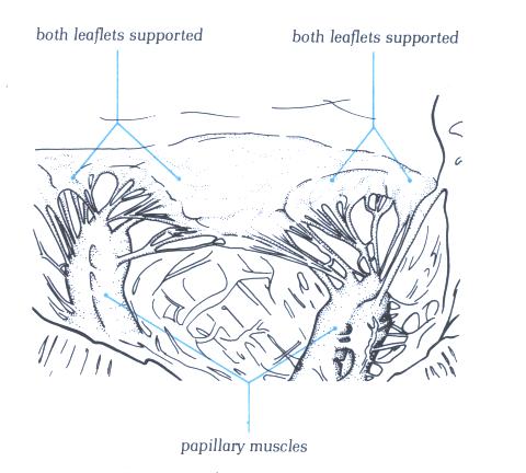
FIGURE 9P-1: Labelling
of structures in figure 9P.
FIGURE 9Q: With
the considerable variation possible in the papillary muscle,
this group of fan-like muscles is in sharp contrast to the pillar-type
muscles in figure 9P.
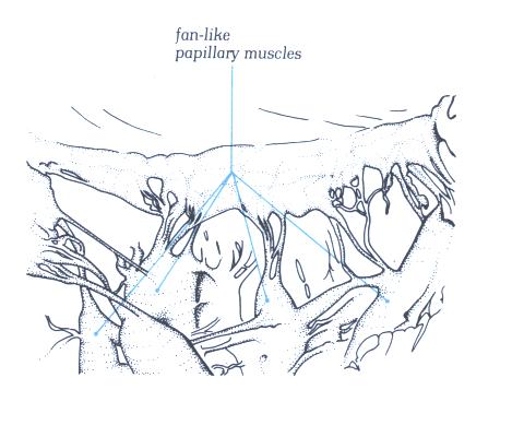
FIGURE 9Q-1: Labelling
of structures in figure 9Q.
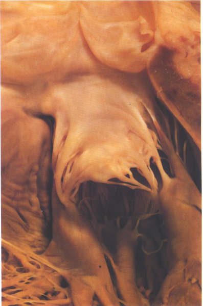
FIGURE 9R: The
anterior leaflet of the mitral valve viewed from the outflow
tract showing the strut chordae.
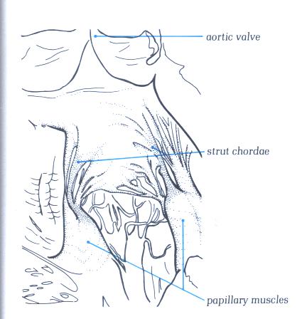
FIGURE 9R-1: Labelling
of the structures in Figure 9R.
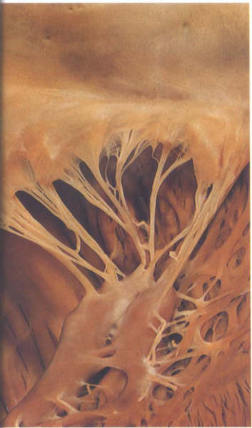
FIGURE 9S: The
posteromedial commissural chordae of the mitral valve.
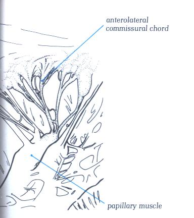
FIGURE 9S-1: Labelling
of the structures in Figure 9S.
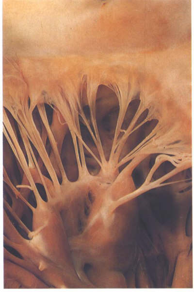
FIGURE 9Sa: The
anterolateral commissural chordae of the mitral valve.
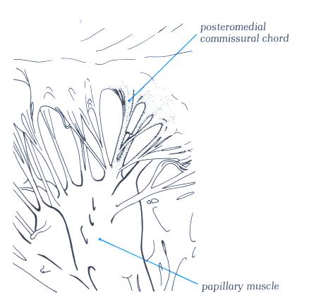
FIGURE 9Sa-1: Labelling
of the structures in Figure 9Sa.
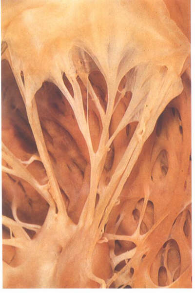
FIGURE 9Sb: Cleft
chorda of the same valve as in figs.9S and 9Sa. Althuogh supporting
a cleft between 2 scallops, it is virtually indistinguishable
from the commissural chords.
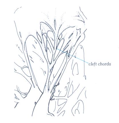
FIGURE 9Sb-1: Labelling
of the structures in Figure 9Sb.
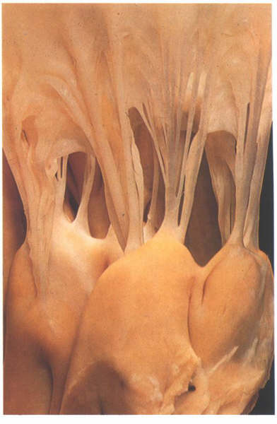
FIGURE 9Sc: Detail
of the attachments of the chordae to the papillary muscles.
the blood disperses into the left ventricle through the interchordal
spaces.
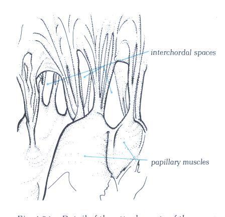
FIGURE 9Sc-1: Labelling
of the structures in Figure 9Sc.
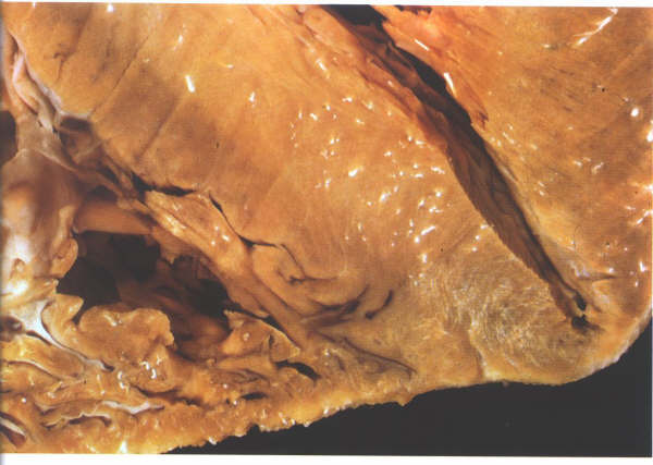
FIGURE 9Sd: Section
of the ventricular apices showing how thin the myocardium is
at this point.
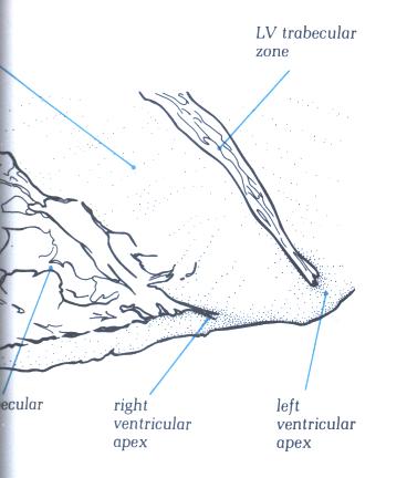
FIGURE 9Sd-1: Labelling
of the structures in Figure 9Sd.
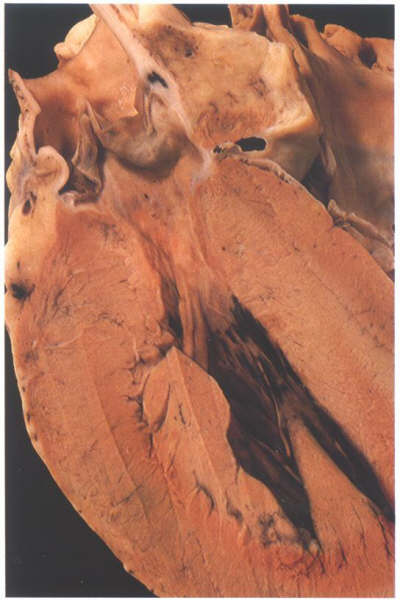
FIGURE 9Se: The
anterior half of the left ventricular outflow tract viewed from
behind. The posterior part is shown in fig. 9Se. Note that the
anterior quadrants are muscular.
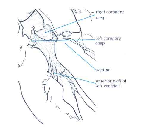
FIGURE 9Se-1: Labelling
of the structures in Figure 9Se.
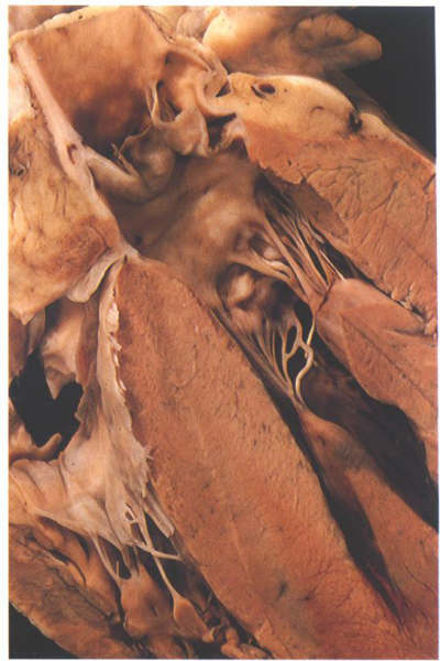
FIGURE 9Sf: The
posterior half of the left ventricular outflow tract shown in
the fig.9Se. Note the continuity between aortic and mitral valves.

FIGURE 9Sf-1: Labelling
of the structures in Figure 9Sf.
FIGURE 9Sg: Frontal
section through a heart showing the considerable angle which
exit between the trabecular and outlet parts of the left ventricle.
FIGURE 9Sg-1: Labelling
of the structures in figure 9Sg.
FIGURE 9Sh: Increase
in the angle between the trabecular and outlet portins leads
to the sigmoid septum of old age (compare with figure 9Sg above).
FIGURE 9Sh-1: Labelling
of the structures in figure 9Sh .
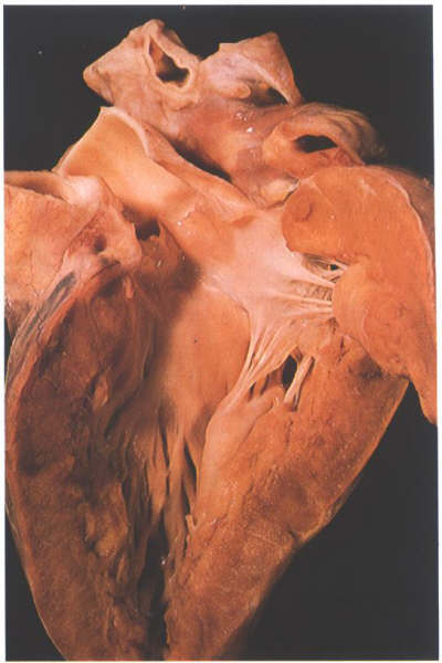
FIGURE 9Si: The
opened left ventricular outflow tract. The relationship of the
aortic cusps to the mitral valve anterior leaflet is variable.
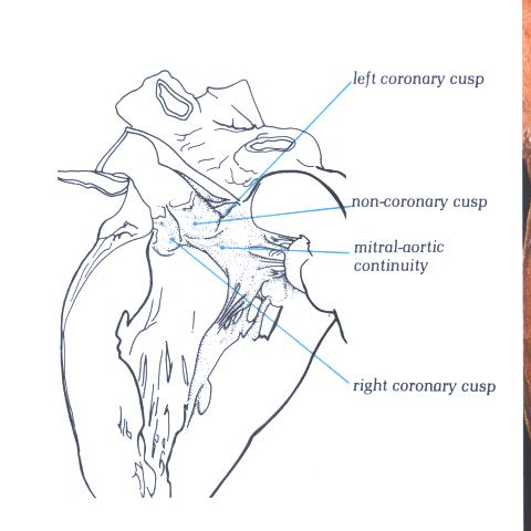
FIGURE 9Si-1: Labelling
of the structures in figure 9Si.
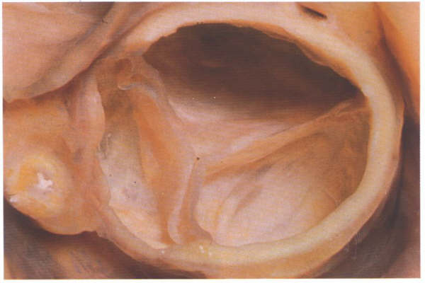
FIGURE 9Sj: Aortic
leaflet viewed from above in the closed position. Note that
the leaflets are not of the same size.

FIGURE 9Sj-1: Labelling
of the structures in figure 9Sj.
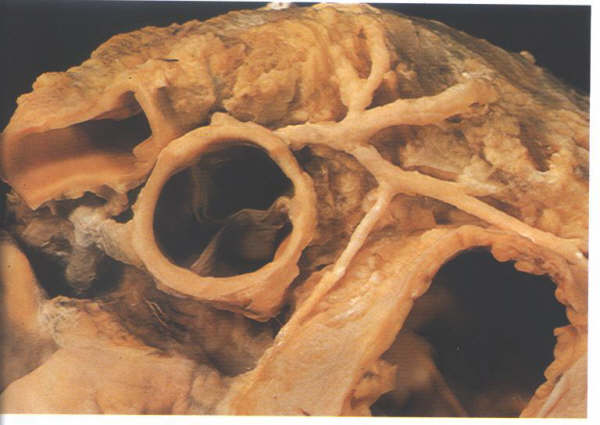
FIGURE 9Sk: The
origin of the coronary arteries enables the leaflets of the
aortic valve to be designated right coronary, left coronary
and non coronary leaflets.
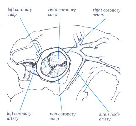
FIGURE 9Sk-1: Labelling
of the structures in figure 9Sk.
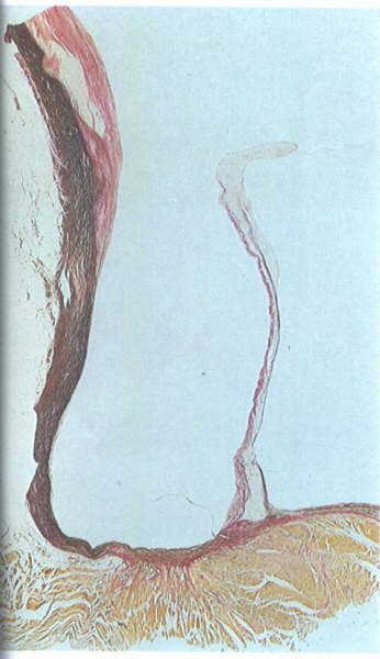
FIGURE 9Sl: Histologic
section showing the origin of the parietal part of an aortic
leaflet from ventricular muscle.
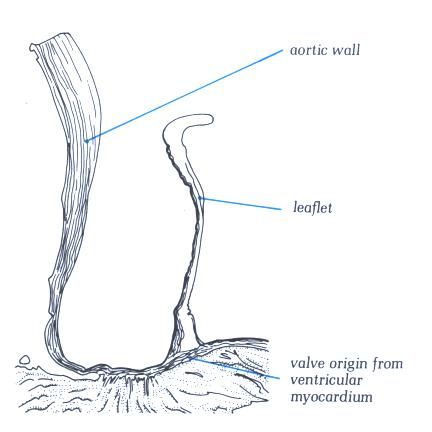
FIGURE 9Sl-1: Labelling
of the structures in figure 9Sl.
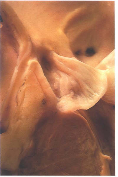
FIGURE 9Sm: Bisection
of the aorta through the origin of a coronary artery. Note that
the valve leaflets closes against the aortic bar and that the
coronary artery ostium is beneath the bar.
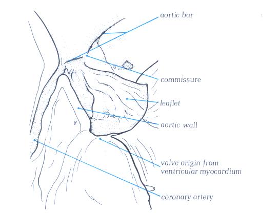
FIGURE 9Sm-1: Labelling
of the structures in figure 9Sm.
FIGURE 9Sn: Section
through the aortic outflow tract from the right side showing
how the right coronary cusp is related to the infundibulum of
the right ventricle.
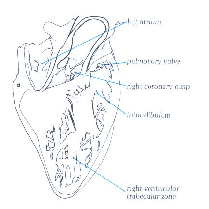
FIGURE 9Sn-1: Labelling
of the structures in figure 9Sn.
FIGURE 9So: A
dissected atrioventricular junction viewed from above showing
how the aortic valve wedges itself between the mitral and tricuspid
valves.
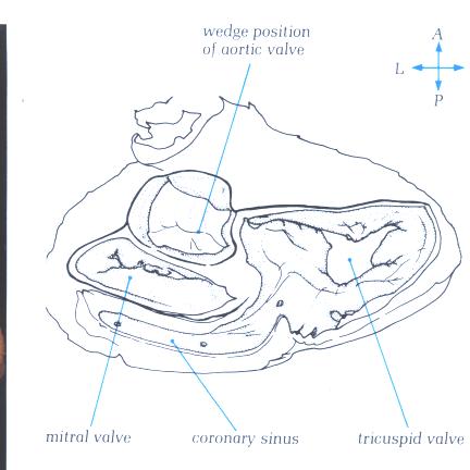
FIGURE 9So-1: Labelling
of structures in figure 9So.
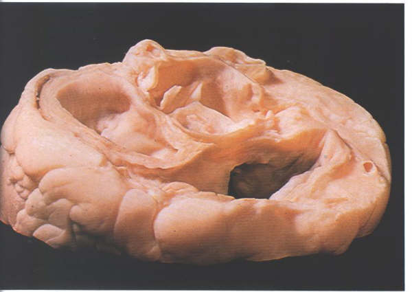
FIGURE 9Sp: Section
through the atrioventricular junction viewed from above and
behind showing the relationship of the non-coronary cusp to
the right atrium.
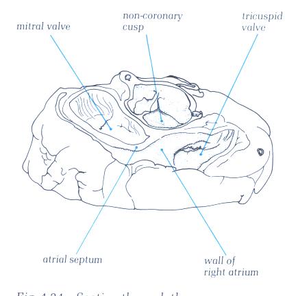
FIGURE 9Sp-1: Labelling
of structures in figure 9Sp.
Left Atrium
The left atrium receives blood from the pulmonary
veins and serves as the reservoir during left ventricular systole
and as a conduit during left ventricular filling. In addition,
left atrial contraction provides a significant increment of
blood to the left ventricle, stretching the ventricle and priming
it for ventricular ejection. This is sometimes referred to as
the "atrial kick" or atrial component of ventricular
filling.
The left atrium is located superiorly, in
the midline, and posterior to the other cardiac chambers (Figs.
1C, 3, 7, and 8). As a consequence of this posterior position,
the left atrium is not normally seen in the frontal roentgenogram
(see figure 8.1 which follows).
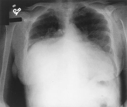
Fig. 8.1
This photograph of an x-ray film of the chest
showing a giant left atrium appeared on the front cover of the
August 7, 2001, issue of Circulation. Note that the huge left
atrium touches the right lateral wall of the chest and not the
left.
( J. Willis Hurst, MD, Division of Cardiology,
Emory University, 1462 Clifton Road, NE, Suite 301, Atlanta,
GA 30322).
In the article by Doctor J. Willis Hurst,
it is emphasizes that the above abnormalities noted on x-ray
films of the chest can be diagnostic of giant left atrium. It
also pointed out that a giant left atrium that occasionally
occurs in patients with rheumatic mitral valve regurgitation
does not occur in patients with mitral regurgitation due to
other causes.
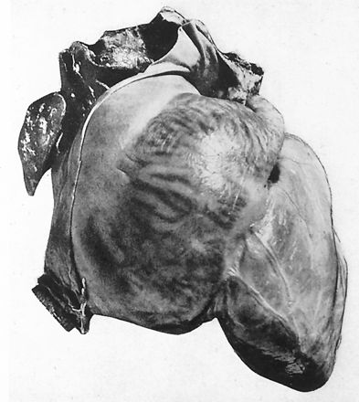
Fig. 8.10 Per
J. Willis Hurst, MD, this photograph was published in the first
edition (1931) of Heart Disease by Dr Paul White. It shows the
heart of a patient with a giant left atrium due to predominate
mitral regurgitation secondary to rheumatic heart disease. The
left atrium held 1760 cc of fluid and the right atrium held
650 cc of fluid. Dr.Hurst felt this was the same heart that
was preserved in a jar in the cardiac museum adjacent to the
cardiac onference room in the Massachusetts General Hospital
in the late 1940s.
Reproduced from White PD. Heart Disease. New
York, NY: MacMillan Company; 1931: 460–461.
The publisher
of Heart Disease is no longer in existence. For this reason
and because the book was published 70 years ago, the photograph
is used under the fair use rules of copyright protection.
Figure 8.11:
Figure 1. Posteroanterior chest x-ray showing near-complete
opacification of the right mid-to-lower lung zones, with a shift
of the mediastinal structures and heart leftward. An underlying
mass lesion could not be excluded. The remaining lung fields
are without evidence of focal consolidation ( Paulo
R. Schwartzman, MD and R.D. White,MD; Circ.2001;page104:e28.)
Figure 8.11:
Figure 2. Cine images of enlarged left atrium due to
mitral valve disease.
Coronal (A) and axial (B) images demonstrate almost complete
filling of the right hemithorax by the left atrium secndary
to mild mitral stenosis, and moderate-to-severe mitral insufficiency.
(Schwartzman PR, White RD. Giant left atrium.
Circulation.. 2001; 104: e28–29).
Giant Left Atrium
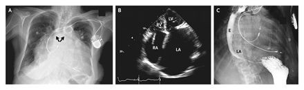
The above images are from the N. ENGL. J. MED 358;19, MAY 8, 2008 by Garrick C. Stewart, M.D. and Anju Nohria, M.D., Brigham and Women's Hospital, Boston, Ma. 02115. The chest radiography (panel A) shows cardiomegaly, splaying of the carina, and an elevated left main bronchus(arrows). An echocardiogram illustrates massive biatrial enlargement(left greater than right), normal ventricular size and function, and moderate mitral and tricuspid regurgitation(Panel B;LA indicates left atrium, LV left ventricle, RA right atrium, and RV right ventricle). An esophagram( panel C) revealed a prominent impression of the left atrium on the esophagus(E),without evidence of obstruction.
These images are presented here to illustrate how the giant left atrium appears utilizing other modalities of imaging.
The esophagus abuts directly on its posterior
surface, while the aortic root impinges on its anterior wall.
The right atrium is located to the right and anterior (Fig.
1-C). The left ventricle is to the left, anterior, and inferior.
The posterior position of the left atrium makes it impossible
to palpate externally unless it is massively dilated. With severe
mitral regurgitation, however, expansion of the left atrium
from the regurgitation and the ejection recoil of the anteriorly
located ventricles may force the heart anteriorly, producing
a late systolic sternal lift. The left atrium usually enlarges
posteriorly and laterally in mitral stenosis or regurgitation,
occasionally even reaching the right or left lateral chest wall
( see figures 8.9 , 8.10 and 8.11 above)
The wall of the left atrium is 3 mm, slightly
thicker than that of the right atrium. Two pulmonary veins enter
posterolaterally on each side, conveying oxygenated blood from
the lungs. Though there are no true valves at the junction of
the pulmonary veins and the left atrium, "sleeves" of atrial
muscle extend from the left atrial wall around the pulmonary
veins for 1 or 2 cm and may exert a partial sphincter-like influence,
tending to lessen reflux during atrial systole or mitral regurgitation
(Fig. 8, 8.1a, 8.1b, and 8.1c ).

Fig. 8.1a,
8.1b, and 8.1c: Two pulmonary veins on each side (one
superior and one inferior). Note the sleeves of atrial muscle
extending into the pulmonary veins 1 to 2 cm. Pictures
obtained by John Sutherland, M.D. Arizona Heart Institute, Phoenix
, Az. using the G.E. 64 slice CT scanner.
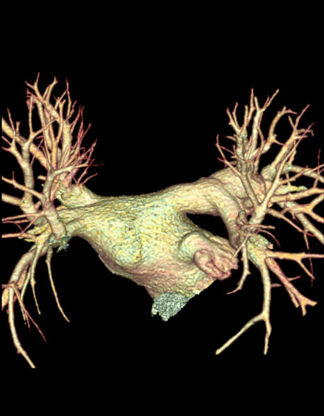
Figure 8.1d
Further view of the pulmonary veins entering
the left atrium. Pictures
obtained by John Sutherland, M.D. Arizona Heart Institute, Phoenix
, Az. using the G.E. 64 slice CT scanner.
The endocardium of the left atrium is smooth
and slightly opaque (Figs. 8 ). Pectinate muscles are present
only in the left atrial appendage, which projects from the anterolateral
left atrium, alongside the pulmonary artery. The atrial septum
is smooth but may contain a central shallow area, corresponding
to the fossa ovalis (Figs. 8).
The smooth-walled part of the left atrium
is larger than the appendage (figure 8.4) and superiorly
receives the four pulmonary veins, two to each side (figures
8.3, and 8.4).
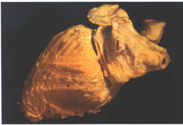
Figure 8.3:
Dissection viewed from behind
showing the left-sided chambers. The atrium is the most posterior
and receicves the four pulmonary veins at its four corners.The
appedage passes forwards to hook round the great arteries.
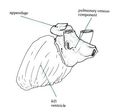
Diagram -
Figure 8.3-a: Drawing
of figure 8.3 above with labelling.
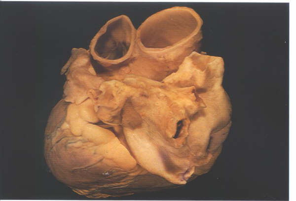
Figure 8.4:
The left atrium in an intact
heart viewed from above and from the left. It shows the pulmonary
veins entering the posterior aspect and the appendage hooking
round the great arteries.
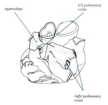
Diagram - Figure 8.4-a:
Drawing of figure 8.4 above with
labelling.
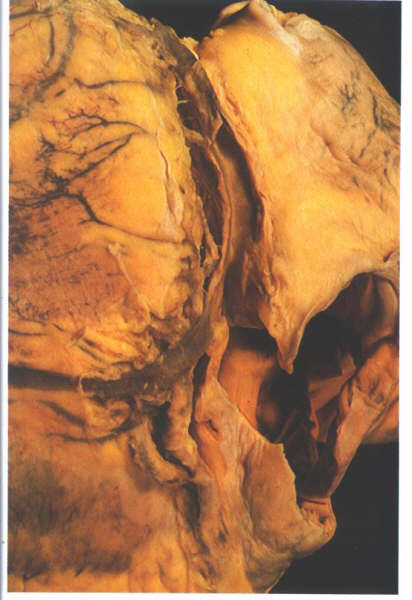
Figure 8.5:
The heart viewed from behind
and oriented in its in situ position. The position of the coronary
sinus is shown in the left artioventricular groove between the
left atrium and the left ventricle.
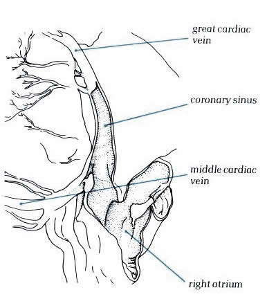
Diagram - Figure
8.5-a: Drawing of figure
8.5 above with labelling.
Inferiorly, the coronary sinus is found along
the posterior wall of the left atrium occupying the left atriooventricular
sulcus (figure 8.5). In hearts with a persistent left superior
vena cava which drains to the coronary sinus, the left-sided
cava forms a channel between the left atrial appendage and the
left pulmonary veins (figure 8.6).
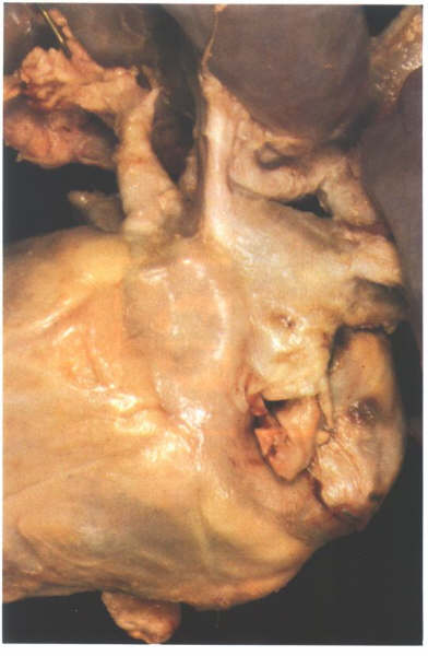
Figure 8.6:
Posterior view of a heart with a persistent left superior vena
cava. The vein runs down between the appendage and the pulmonary
venous portion to drain into the right atrium via the coronary
sinus.
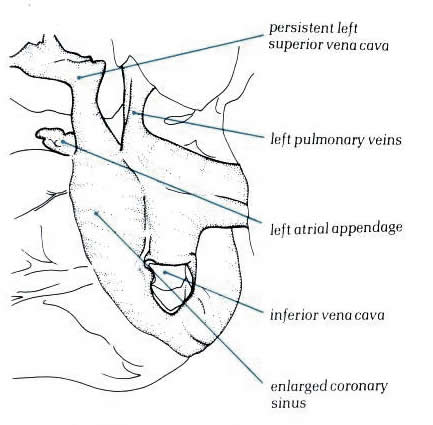
Diagram - Figure
8.6-a: Drawing
of figure 8.6 above with labelling.
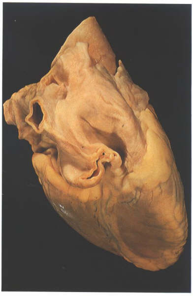
Figure 8.7:
View of the heart from behind
showing the prominent groove (Waterston's groove) between the
right pulmonary veins and the right atrium.
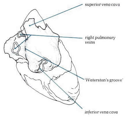
Diagram - Figure
8.7-a:
Drawing of figure 8.7 above with labelling.
In some hearts, a fibrous strand representing
the site of the left cava present during development
can be observed in a similar position. The lower end of the
strand is frequently patent,forming the oblique vein of the
left atrium, which drains into the coronary sinus.To the right,
the right pulmonary veins are separated from the right atrium
by the sulcus marking the site of the limbus of the fossa ovalis
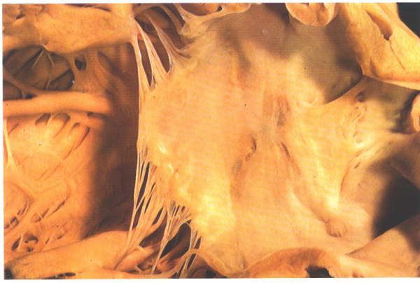
(figure 8.7). Internally, the appendage of the left atrium is
trabeculated as is the right appendage; but the junction of
the trabeculae and the venous atrium on the left is not marked
by the presence of any structure comparable to the crista terminalis,
and the trabeculae are less pronounced (figure 8.8 and 8.8a).
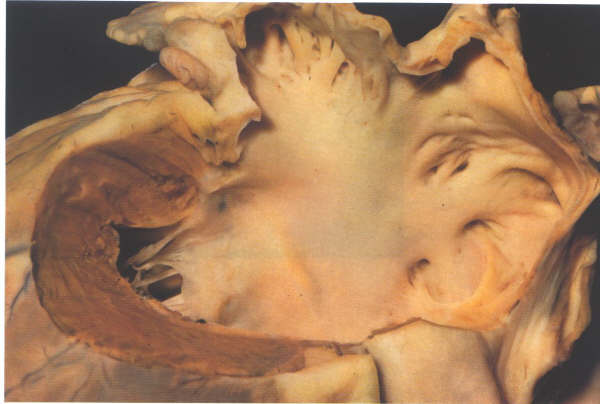
Figure. 8.8:
The left atrium has a
roof, a floor, a posterior wall, an anterior wall and a septal
surface.
The left atrium has a roof, a floor, a posterior
wall, and a septal surface. The roof is formed by the tissue
between the four pulmonary veins and this wall continues over
into the posterior surface. The floor is the orifice of the
mitral valve, considered along with the valve in its separate
section. Anteriorly is thesmall ostium of the atrial appendage,
abutting inferiorly on the mitral orifice. The left atrium also
has an extensive anterior wall composed solely of roughened
musculature which lies posterior to the aorta (figs. 12and 12a).
The septal surface is oblique and consists
of the left atrial surface of the fossa ovalis.There is no rim
to the fossa ovale on the left atrial side; but anteriorly,
the flap valve is usually plastered down onto the anterior wall,
the junction being marked by a characteristic rough area (fig.8.10a).
When the septum is transilluminated, it is found that the floor
of the fossa ovalis visible in the right atrium is posterior
to the rugose area of the left atrial wall (compare figs.4.10i-1,4.10j-1,
8.11-a, 8.10). When the anterior part of the flap valve is not
adherent to the anterior atrial wall, then probe-patent foramen
ovale results(fig.8.11).
By comparison of the transilluminated figures(figs.4.10j-1
and 8.11-a ) and examination of the cross sections (figs.4.10f
, 8.12 and 8.13) it can be seen that the interatrial septum
occupies only a small part of the atrial walls described as
septal 'surface'. Much of the superior limbus is simply the
infolded sulcus between the superior vena cava and the right
pulmonary veins(Fig.4.10i-1).The anterior limbus is mostly the
anterior atrial wall and in this position is in direct relation
to the anterior root of the aorta, being separated from it by
the transverse sinus of the pericardium (fig.8-12).The inferior
limbus is in part true atrial septum; but, owing to the origin
of the tricusp valve from the septum being much more towards
the ventricular apex than that of the mitral valve (fig.8.13),
much of the inferior limbus is positioned between the right
atrium and the inlet portion of the left ventricle. Similarly,
the anterior part of the limbus overlying the the central fibrous
body is continuous with the atrioventricular component of the
membranous septum and is located between right atrium and the
aortic outflow tract (fig.8.14). The area around the coronary
sinus is related
directly to atrioventricular sulcus tissue.Consequently, it
is not part of the septum (figs.8.15 & 8.16).
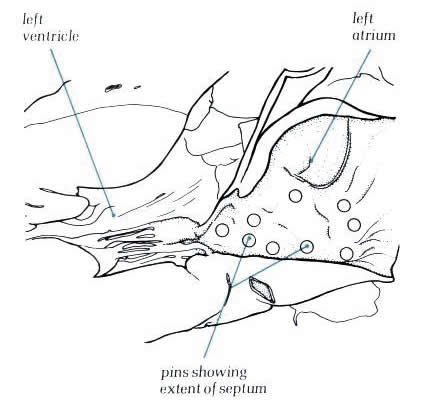
Finally, the area of the posterior limbus
is directly continuous with the wall of the inferior vena cava
and only a small part is true atrial septum.The small area of
the true septum can be illustrated by inserting markers at its
margins (figs.8.17 & 8.18) and by removing the septum (figs.8.19
and 8.20). The importance of this is largely surgical, since
incisions placed outside the area of the septum will carry the
surgeon outside the heart. Similarly,'septal' puncture performed
at catheterization in a position anterior to the area of the
fossa ovalis where there is frequently a recess in the anterior
wall of the right atrium(figs.8.21 and 8.21a ) will produce
cardiac rupture. A catheter lodged in this recess can easily
simulate a position in the fossa ovalis. If pushed through the
recess, the catheter will pass through the transverse sinus
and into the aorta or pulmonary artery.
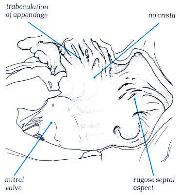
Diagram - Fig.
8.8a
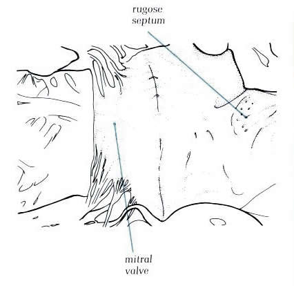
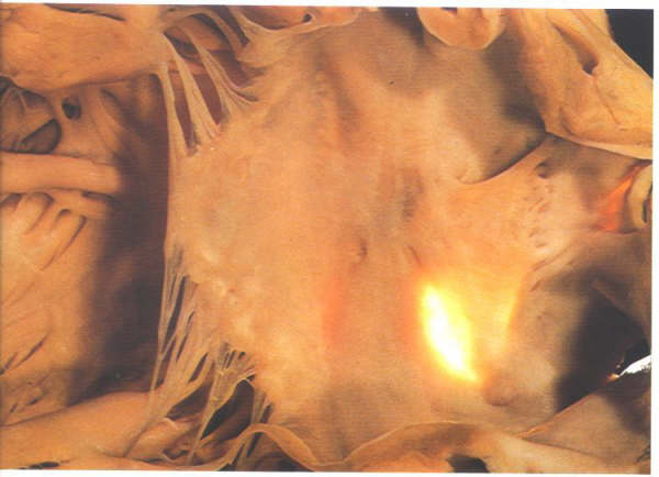
Figure
8.10: The septal surface of the left atrium and the vestibule
of the mitral valve. Note the roughened aspect of the septal
surface which is the flap valve of the fossa ovalis.
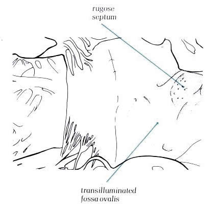
Diagram
- 8.10a. The same specimen
as in fig.8.10 transilluminated
from the right side. The fossa ovalis is well posterior and
inferior to the flap valve noted on the left septal surface.
Figure
8.11a: The same specimen as in figure 8.10 transilluminated
from the right side. The fossa ovalis is well posterior and
inferior to the flap valve noted on the left septal surface.
Diagram
- Figure 8.11b - labelling
of fig.8.11-a.
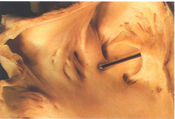
Figure
8.12: A probe patent foramen with a probe inserted from
the right atrium between the limbus and the flap valve. The
right side of this heart is shown in figure 4.10k-1.
Diagram
- Figure 8.12a with
labelling
Figure
8.13: Section through the atrial and ventricular septa
viewed from behind. Part of the inlet septum interposes between
the left ventricular inlet and the right atrium.
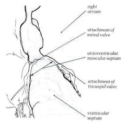
Diagram - Figure
8.13a with labelling.
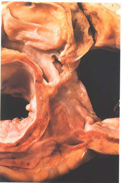
Figure
8.14: Oblique section through the aortic outflow tract
showing its relationship to the right atrium. This area is the
atrioventricular mmembranous septum.
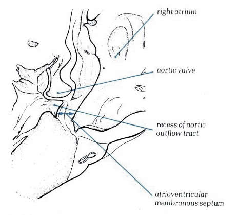
Diagram - Figure
8.14a with labelling.
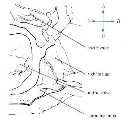
Figure
8.15: Transverse section viewed superiorly through the
base of the atrium showing the floor of the coronary sinus and
the aortic outflow tract.
Diagram
- Figure
8.15a: Drawing of fig.8.15 with labelling.
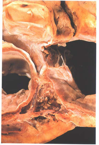
Figure
8.16: The heart shown in fig.8.15 after removal of the
floor of the coronary sinus. This is not septum but the atrioventricular
sulcus.
Diagram
- Figure
8.16a: Drawing of fig.8.16 with labelling.
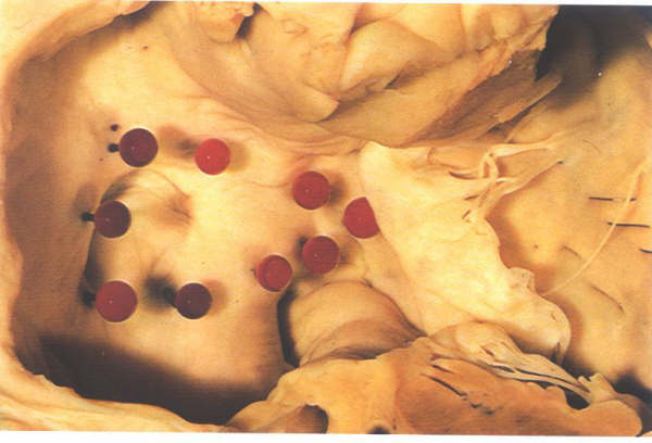
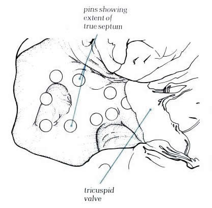
Figure
8.17: The right aspect of the atrial "septum".
Pins have been inserted to show the true confines of the interatrial
septal surface. Thsi is considerably smaller than may be anticipated.
Diagram
- Figure
8.17a: Drawing of fig.8.17 with labelling
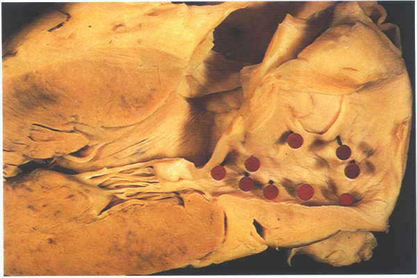
Figure
8.18: Left atrial view of the septum shown in fig.8.17
Diagram
- Figure
8.18a: Drawing of fig.8.18 with labelling.
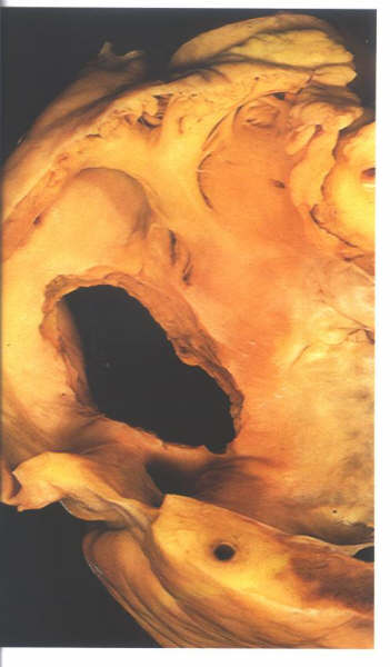
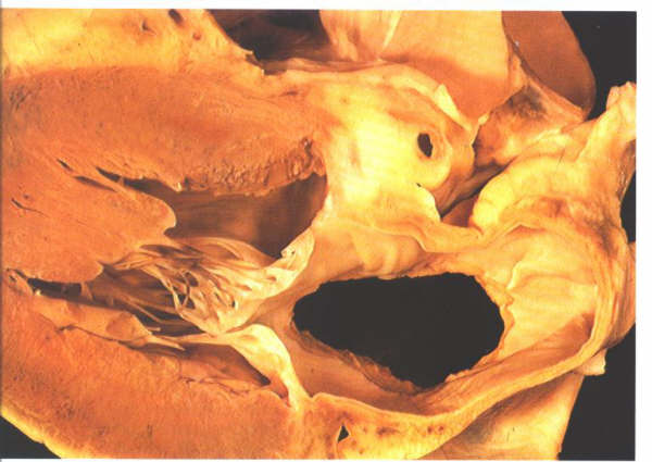
Figure 8.19: Further
view of the right side of the atrial "septum". The
true interatrialsurface has been removed to show the extent
of the setum.
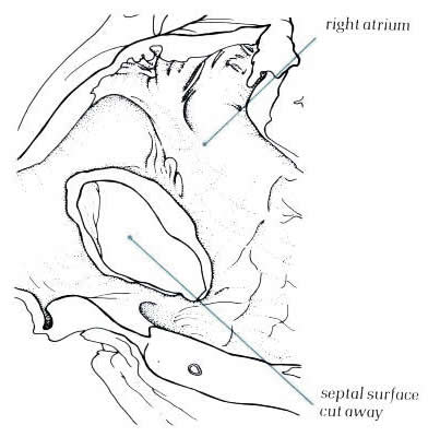
Diagram - Figure
8.19a: Drawing
of the 8.19 with labelling
Figure
8.20: Left atrial view of the septum shown in fig.8.19.
Diagram
- Figure
8.20a: Drawing of fig.8.20 with labelling.
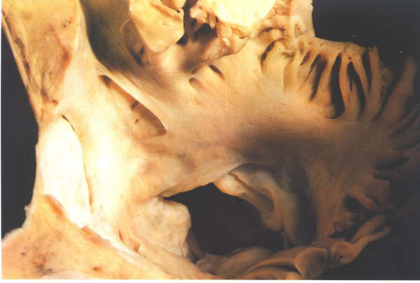
Figure 8.21:
Transverse section superiorly
viewed through the fossa ovalis. In front of the anterior limbus
of the fossa there is a fold of endocardium producing a crevice
in the anterior atrial wall.
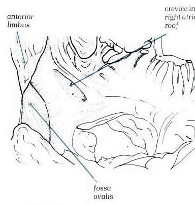
Diagram - Figure
8.21a: Drawing
of the fig.8.21 with labelling
Left Ventricle
The left ventricle receives blood from the
left atrium during ventricular diastole and ejects blood into
the systemic arterial circulation during ventricular systole
(Figs. 8 to 9 and 11). The left ventricle is roughly bullet
shaped with the blunt tip directed anteriorly, inferiorly, and
to the left, where it contributes, with the lower ventricular
septum, to the apex of the heart. Although the left ventricle
forms the lower left lateral cardiac border in the frontal roentgenogram,
the major portion of its external surface is posterolateral
(Fig. 1). The left ventricle is posterior and to the left of
the right ventricle and inferior, anterior, and to the left
of the left atrium. The left ventricular chamber is approximately
an ellipsoidal sphere, surrounded by thick muscular walls measuring
8 to 15 mm, or approximately two to three times the thickness
of the right ventricular wall. The tip of the left ventricular
apex is often thin, sometimes measuring 2 mm or less. The medial
wall of the left ventricle is the ventricular septum, which
is shared with the right ventricle (Figs. 2, 8 to 11). The septum,
which is roughly triangular in shape with the base of the triangle
at the level of the aortic cusps, is entirely muscular except
for the small membranous septum, located superiorly just below
the right coronary and the posterior coronary cusps (Figs.8
and 12). The upper third of the septum is smooth endocardium.
The remaining two-thirds of the septum and the remaining ventricular
walls are ridged by interlacing muscles, the trabeculae carneae.
The ventricular wall exclusive of the septum is often referred
to as the free wall of the left ventricle.
The anteromedial leaflet of the mitral valve,
which is the larger and more mobile of the two mitral leaflets,
extends from the top of the posteromedial septum across the
ventricular cavity to the anterolateral ventricular wall and
separates the left ventricular cavity into an inflow and an
outflow tract (Figs. 11 and 13). The funnel-shaped inflow tract,
which is formed by the mitral annulus and by both mitral leaflets
and their chordae tendineae, directs the entering atrial blood
inferiorly, anteriorly, and to the left (Figs. 11 and 13). The
outflow tract, surrounded by the inferior surface of the anteromedial
mitral leaflet, the ventricular septum, and the left ventricular
free wall, orients the blood flow from left ventricular apex
to the right and superiorly at an angle of 90° to the inflow
tract. With the onset of ventricular systole, both mitral leaflets
are propelled together and upward, converting the entire left
ventricle into an expulsion chamber. The apical portion of the
left ventricle is characterized by fine trabeculations.
FIGURE 14
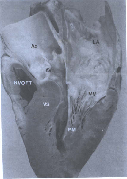
Long axis view of left ventricle
showing continuity of aortic (AV) and mitral (MV) valves(arrows)
and chordae tendineae(CT) of MV. Ao=aorta; LA= left atrium;
LV= left ventricle; RVOFT = right ventricular outflow tract.
Cardiac Valves
The heart contains four cardiac valves: two
semilunar and two atrioventricular. The two semilunar valves,
aortic and pulmonic, guard the outlet orifice of their respective
left and right ventricles. The two AV valves, mitral and tricuspid,
guard the inlet orifice of their respective left and right ventricles.
The four cardiac valves are surrounded by fibrous tissue forming
partial or complete "rings" (valve annulus). These
fibrous rings join to form the fibrous skeleton of the heart,
to which also are attached atrial and ventricular myocardium.
The area between the septal leaflet of the tricuspid valve,
the anterior leaflet of the mitral valve, and the posterior
or noncoronary cusp of the aortic valve forms one part of the
central fibrous body. The remaining portion is made up of fibrous
tissue connecting the left aortic cusp and the anterior leaflet
of the mitral valve.
Histological Structure
Each cardiac valve has a central collagenous
core, the fibrosa, which is continuous with the collagen of
the cardiac skeleton and of the chordae tendineae. Both sides
of the fibrosa are covered by loose fibroelastic tissue, usually
containing mucopolysaccharides, and the entire valve is covered
by endothelium. The endothelium and connective tissue of the
AV valves are continuous with atrial and ventricular endocardium,
and those of the semilunar valves are continuous with the aortic
and pulmonary intima. Gross and Kugel have proposed that the
loose connective tissue on the atrial aspect of the AV valves
be termed the atrialis, that on the ventricular the arterialis.
Smooth and striated cardiac muscle may extend onto the proximal
one-third of the atrialis in the AV valves and often contains
blood vessels. The distal two-thirds of the normal AV valve
and all the semilunar valve are avascular.
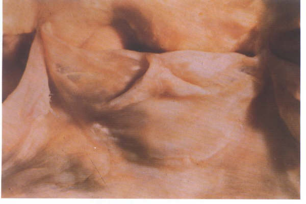
Semilunar Valves
The semilunar aortic and pulmonary valves
are similar in configuration, except the aortic cusps are slightly
thicker. They are situated at the summit of the outflow tract
of their corresponding ventricle, the pulmonary valve being
anterior, superior, and slightly to the left of the aortic valve
(Figs. 3, 5, 8, 10, 14, 16 to 18). Each valve is composed of
the three fibrous cusps. The pulmonary valve differs from the
aortic valve by having no discrete annulus or fibrous ring.
The U-shaped convex lower edges of each cusp are attached to
and suspended from the root of the aorta or pulmonary artery,
with the upper free valve edges projecting into the lumen. The
cusps circle the inside of the vessel root.
Each semilunar valve consists of three equal-sized
or nearly equal-sized semicircular cusps. Each cusp is attached
by its semicircular border to the wall of the aorta or pulmonary
trunk. The small space between attachments of adjacent cusps
is called a commissure. Each semilunar valve has three commissures.
The three commissures lie equally spaced around the aorta or
pulmonary trunk, and the circumference connecting these points
has been termed the sinotubular junction, which may also be
described as the portion of the great vessel separating the
sinuses of Valsalva from the adjacent tubular portion of
the great artery. In the aorta a distinctive circumferential
"hump" or line marks this junction, originally described
by Leonardo da Vinci as the "supraaortic ridge." Each
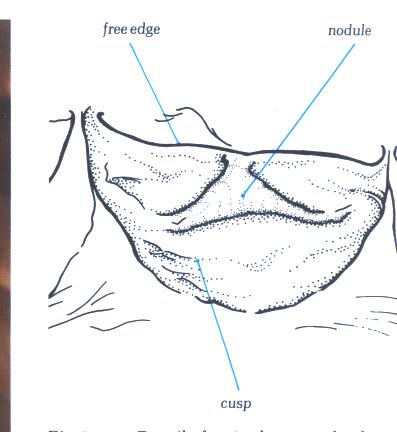
of the ventricular surfaces of the semilunar cusps has a small
nodule [much more prominent on the aortic valve (noduli Arantii)]
in the center of the free edge marking the contact sites of
closure (Figs. 17A, 17B, 17B-1, 17C, 17C-1, 17D, 17D-1, 17E,
17E-1, 17F, 17F-1,17G, 17G-1, 18 and 22). Behind each cusp the
vessel wall bulges outward, forming a pouchlike dilatation known
as the sinus of Valsalva. The free edge of each cusp is concave,
with a nodular interruption at the center of the cusp, the nodulus
Arantii. The portion of the cusp adjacent to the rim is not
as thick and may normally contain small perforations. During
ventricular systole, the cusps are passively thrust upward away
from the center of the aortic lumen. During ventricular diastole,
the cusps fall passively into the lumen of the vessel as they
support the column of blood above. The noduli Arantii meet in
the center and contribute to the support of the leaflets. The
geometry of the cusps and the strong fibrous tissue support
provide excellent approximations of the cusps and prevent regurgitation
of blood.
The anatomy of the two AV valves is considerably
more complex than the anatomy of the semilunar valves (Figs.
16, 5, 6, 8,14, and 19 to 22). Both AV valves consist of leaflets
(two mitral and three tricuspid), chordae tendineae, papillary
muscles (two or three, respectively), and valve annuli. The
leaflets are demarcated by commissures located along the valve
annular attachment. The anterior leaflet of each of the AV valves
is the largest and is roughly semicircular in shape. The posterior
mitral leaflet and the posterior and septal tricuspid leaflets
have shorter annulus to free edge distances but longer basal
attachments, compared to the respective anterior leaflet. Complex
chordal structures arise from papillary muscles or directly
from ventricular myocardium and insert onto the free edge and
several millimeters from the margin on the ventricular surface.
The annular structure of the mitral valve primarily surrounds
the posterior leaflet, while the anterior leaflet does not have
a true annulus but is continuous with the wall of ascending
aorta, aortic valve, and membranous ventricular septum. The
annulus of the tricuspid is nearly circumferential, is larger
than the mitral annulus, and lies at a lower level (i.e., more
apical) than the mitral annulus. On the atrial surface of the
AV valves, 0.5 to 1.0 cm from the free edge, is a line of nodular
thickening (more prominent on the mitral valve), marking the
contact points of closure.
Figure 17A
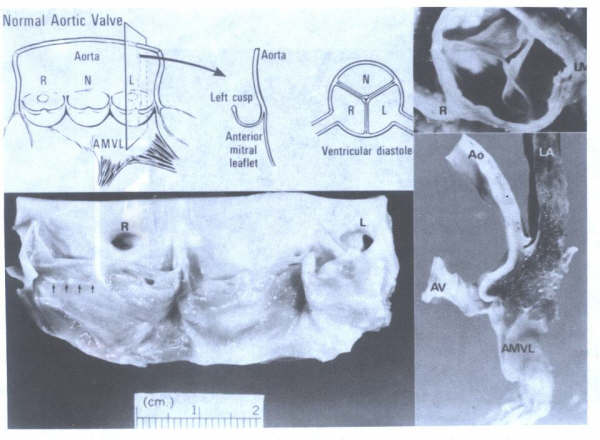
Morphology of the normal aortic valve.
AMVL= anterior mitral valve leaflet. AMVL = anterior mitral
valve leaflet; Ao = aorta; AV = aortic valve; LV = left main;
N = noncoronary cusp; LA = left atrium; R = right; RC = right
coronary artery. Arrows point to line of closure. Portion of
aortic cusp above the line of closure is called the lunula.
FIGURE 17B
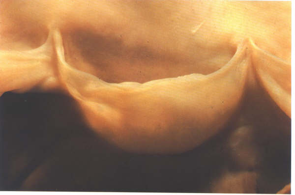
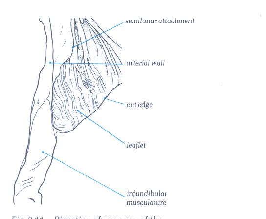
The morphology of an arterial cusp.
FIGURE 17B-1
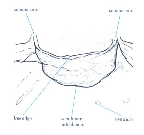
The labelling of the structures in
17B
FIGURE 17C
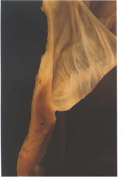
Bisection of one cusp of the pulmonary
valve showing its attachment to its arterial muscular junction.
FIGURE 17C-1
Labelling of structures in Figure
17C above.
FIGURE 17D
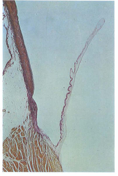
Histology of valve shown in fig. 17C.
FIGURE 17D-1
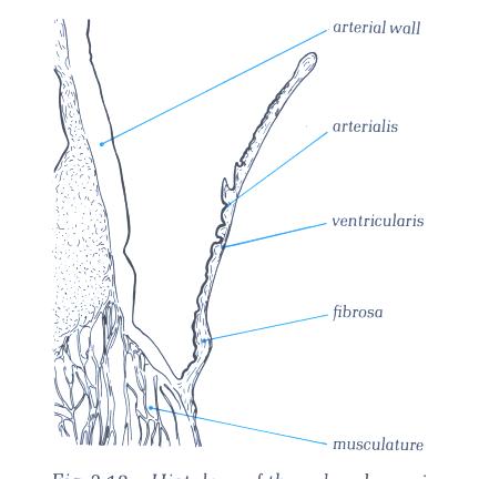
Labelling of structures in fig. 17D.
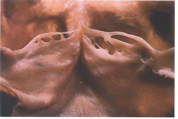
FIGURE 17E
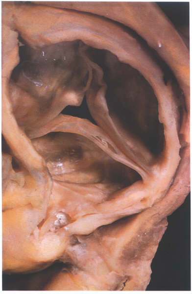
The aortic valve viewed from the aortic
aspect showing how the nodules of the semilunar cusps meet together
when it is in the closed position.
FIGURE 17E-1
Labelling of structures in figure
17E.
FIGURE 17F
Details of a single arterial valve
cusp from an old person showing the well developed nodule.
FIGURE 17F-1
Labelling of the structures in fig.17F.
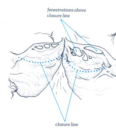
FIGURE 17G
As with the atrioventricular valve,
arterial valves close some distance away from their free edge.
the area between the line of closure and the free edge can be
fenestrated as shown here.This is a normal finding.
FIGURE 17G-1
Labelling of structures in fig.17G.
FIGURE 18
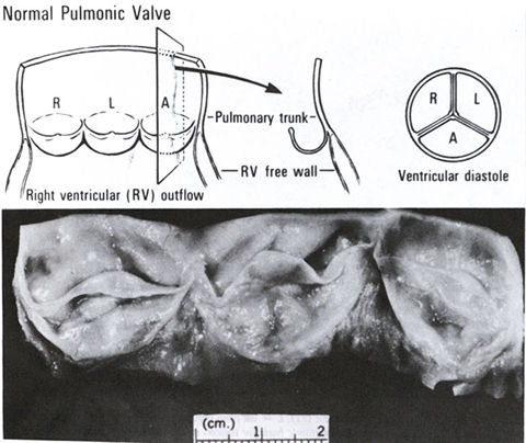
Morphology of the normal pulmonary
valve. A = anterior; L = left; r = right.
Figure 16
Schematic anteroposterior view of
heart with the atria removed. The components of the orientation
of the leaflets of each valve are shown.
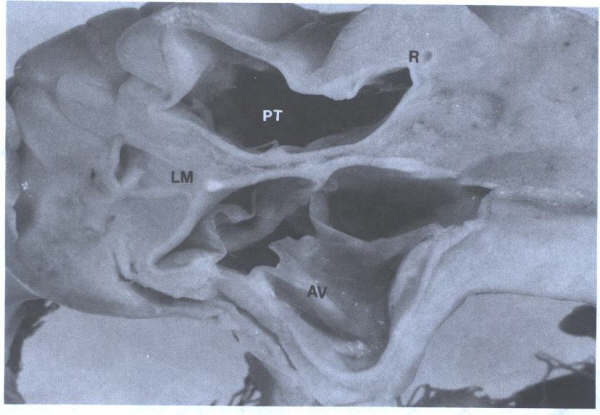
FIGURE 15
Short-axis view of the three-cuspid
aortic valve (AV) and the pulmonary trunk(PT). L=left main coronary
ostium; R=right coronary ostium.
FIGURE 10
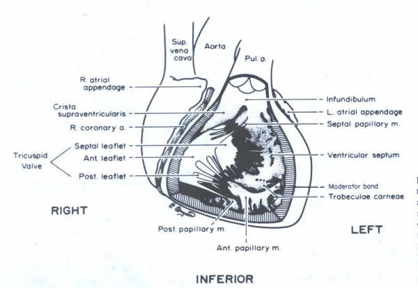
Schematic representation of a frontal
view of the heart. The anterior right ventricular wall has been
removed to demonstrate the orientation of the tricuspid valve
and the papiilary muscles. The anterior papillary muscle is
sectioned. The trabeculated inflow portion of the right ventricle
is contrasted with the smooth infundibular (outflow) area.
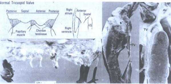
FIGURE 22
Morphology
of the normal tricuspid valve. AV = aortic valve; RA = right
atrium; RVFW = right ventricular free wall; TV = tricuspid valve;
VS = ventricular septum. tic valve; RA = right atrium; RVFW
= right ventricular free wall; TV = tricuspid valve; VS = ventricular
septum. (From Hurst’s The Heart
,Eighth edition, page 73.)
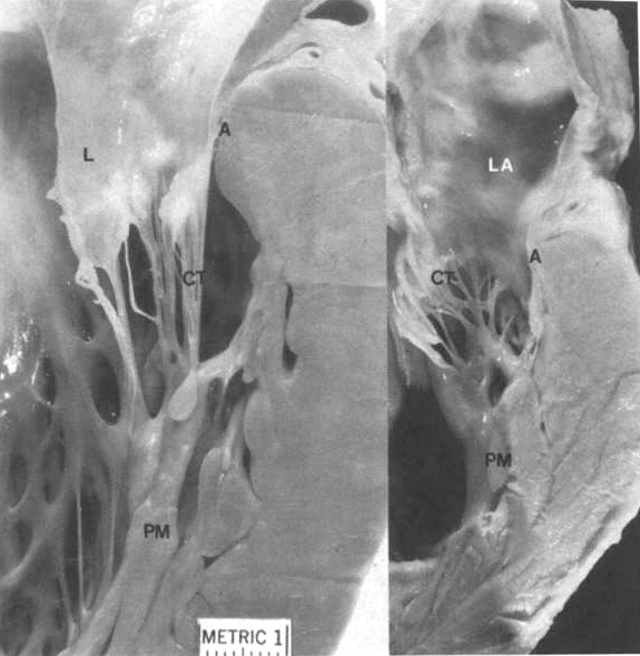
Figure22A
Mitral valve apparatus. Left: Chordae
tendineae (CT); leaflet (L); annulus (A);papillary muscle(PM).
Right; Left atrium(LA). Note the inter chordal connections(arrows)
and chordal connections from both anterior and posterior mitra
lleafelts to the posteomedial papillary muscle(right).
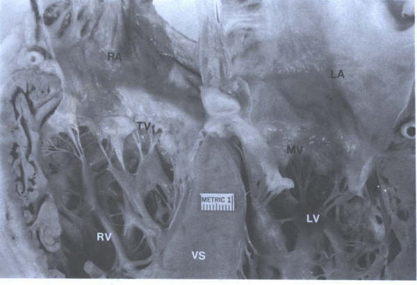
Figure 22B
Four-chamber view showing mitral and
tricuspid valves.The annulus of the tricuspid valve is more
spiral than the annulus of the mitral valve (MV). LA = left
atrium; LV = left ventricle;RA = right atrium;RV = right ventricle;
VS = ventricular septum.
Papillary Muscles
The papillary muscles of both ventricles are
located below the commissures of the AV valves. These muscles
project from the trabeculae carneae and may be single, bifid,
or occasionally a row of muscles arising from the ventricular
wall. In the left ventricle the two groups of papillary muscles,
located below the anterolateral and posteromedial commissures,
arise from the junction of the apical and middle third of the
ventricular wall (Figs. 7 to 10, 14, 15, 19, 20, and 23). In
the right ventricle there are usually three papillary muscles
(Figs. 9 and 10). The largest is the anterior papillary muscle,
which is found below the commissure between the anterior and
posterior leaflets, originating from the moderator band as well
as from the anterolateral ventricular wall. The posterior papillary
muscle lies beneath the junction of the posterior and septal
leaflets. A small septal papillary muscle, originating from
the wall of the infundibulum, tethers the anterior and septal
leaflets high against the infundibular wall. At times this muscle
is virtually absent, and the chordae tendineae arise from a
small tendinous connection to the infundibulum. The septal leaflet
of the tricuspid valve usually has extensive attachments to
the ventricular septum. The papillary muscles, because of their
relatively parallel alignment to the ventricular wall and their
chordal attachments to two adjacent valve leaflets, pull the
leaflets of the mitral valve and tricuspid valve together and
downward at the onset of isovolumic ventricular contraction.
Figure 23
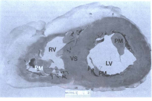
Short-axis view of ventricles showing
papillary muscles (PM) of mitral valve (PM black) and tricuspid
valve (PM white). LV = left ventricle; RV = right ventricle;
VS = ventricular septum
Chordae Tendoneae
Strong cords of fibrous tissue, the chordae
tendineae, spring from the tip of each papillary muscle (Figs.5a,
6, 8, 14, 22a, and 22b). They often subdivide and interconnect
before they attach to the two leaflets directly above. The chordae
may attach directly into a fibrous band running along the free
edge of the valves or they may become incorporated into the
ventricular surface of the leaflet a few millimeters back from
the edge. Additional chordae run directly from the ventricular
wall into the undersurface of the posterolateral leaflet of
the left ventricle and the septal and posterior leaflets of
the right ventricle. The chordae tendineae, by their attachments
to most of the free valvular border and by their numerous cross
connections, allow the valve leaflets to balloon upward and
against each other and evenly distribute the forces of ventricular
systole. Dysfunction or rupture of a papillary muscle or rupture
of a chorda tendinea may undermine the support of one or more
valve leaflets, producing regurgitation.
Endocardium
Endocardium endothelium appears to share many,
if not all, of the many functions of vascular endothelium described
below. A newly found agent from endocardial endothelial cells
that prolongs myocardial contraction has been provisionally
referred to as "endocardin." The prolongation of contraction
by endocardin can be overridden by stimulation of endothelium-derived
relaxing factor (EDRF), which shortens the duration of contraction.
Pericardium
The heart is enclosed by the pericardium,
the two surfaces of which can be visualized by considering the
heart as a fist that is plunged into a large balloon or serous
pericardium (Figs.1 and 24). The surface of the balloon in intimate
contact with the fist is analogous to the visceral pericardium
or epicardium. This surface encases the heart, extending several
centimeters onto each of the great vessels. It is then reflected
back, as is the outer surface of the balloon, to form the parietal
pericardium, which is fused to the fibrous pericardium to form
the fibrous layer. The two pericardial surfaces are lined by
smooth, glistening serous tissue and are separated by a thin
layer of lubricating fluid, which allows the heart to move freely
within the parietal pericardium. The parietal pericardium is
attached by ligaments to the manubrium, the xiphoid process,
the vertebral column, and the diaphragm. There is normally about
10 to 50 mL of thin, clear pericardial fluid, which moistens
the contracting surfaces of the visceral and parietal pericardium.
Four recesses are frequently present in images or examination
of the pericardial space: the superior sinus, the transverse
sinus, the postcaval recess, and the oblique sinus.
TOMOGRAPHIC VIEWS OF NORMAL HEART:
ANATOMIC BASIS FOR VARIOUS CARDIAC IMAGING
TECHNIQUES
During the last several years, dramatic developments
have taken place in the diagnosis of cardiovascular disorders
in the area of cardiac imaging techniques. From a previous era
of imaging by silhouettes (chest roentgenography, fluoroscopy,
angiocardiography), we have emerged into an era of imaging by
tomographic scanning [echocardiography, radionuclide tomography,
computed tomography (CT), magnetic resonance (MRI)]. An understanding
of tomographic anatomy is the foundation for proper use and
interpretation of these new imaging modalities.
Position of Heart and Tomographic Axis
New tomographic imaging techniques result
in various depictions of the heart that have similarities and
differences. The major similarity in the techniques is the planar
method of cardiac sectioning. The major difference in these
various tomographic techniques is the axis of sectioning relative
to the position of the heart in the thorax. Twodimensional echocardiographic
imaging cuts the heart in transverse and longitudinal planes
perpendicular and parallel to the heart itself (Fig. 25). The
heart serves as the axis of tomographic sectioning. The cavities
and chamber walls are sectioned perpendicular and/or parallel
to their respective axis. In contrast, CT and MRI cut the thorax
in transverse and longitudinal planes. The body serves as the
axis of tomographic sectioning. The heart sits in an oblique
position relative to the thorax: The atria are located posteriorly
and only slightly superiorly; the cardiac apex is directed leftward,
anteriorly, and somewhat inferiorly; and the atrial and ventricular
septae and AV valves are directed anteriorly and somewhat inferiorly.
Thus, the right atrium is a right lateral chamber, the left
atrium is a midline posterior chamber, the right ventricle is
an anterior chamber, and the left ventricle is a posterior chamber.
Sectioning the heart in tomographic planes using the thorax
as the axis of reference necessarily results in "distortions"
of cardiac cavities, valve structures, and thickness of chamber
walls. Oblique sectioning of the cavities and chamber walls
may not provide precise anatomic correlates but produces truncated
or inflated measurements. Technical changes in CT and MRI presently
under development will permit tomographic cardiac sectioning
using the heart as the axis of reference. In contrast to imaging
modalities using the thorax as the axis of sectioning, echocardiography
uses the heart as the axis of sectioning.
Thus, precise anatomic correlates can be made
in terms of measurements of wall thickness and chamber sizes.
Debate among pathologists and anatomists concerning the "proper
anatomic orientation" and "display" of tomographic
cardiac images centers around the principle of reference axis.
Arguments that depiction of the heart in an echocardiographic
four-chamber view ("valentine shape") is "unconventional"
and "non-anatomic" are based upon tomographic imaging
that uses the body as the reference axis. When one uses the
heart as the reference axis, however, the echocardiographic
four-chamber view is quite conventional and anatomic.
Preparation of Necropsy Heart and Methods
of Cutting to Display Tomographic Anatomy
At necropsy, planar sectioning of the heart
requires formalin fixation with or without perfusion for 12
to 24 h before cutting. If pressure fixation is not available,
gentle "stuffing" of the atria with paper towels can
help distend these chambers. The paper towels should not be
placed through the AV valves as this will abnormally distort
the valve leaflets. Adult as well as infant hearts can be sectioned
in tomographic planes if prepared by the above described methods.
Actual tomographic cutting of the heart can be done with the
use of a large 12- to 16-in knife, which allows smooth, straight
sectioning. Sectioning the heart in tomographic planes
without formalin fixation will result in irregular rough cavity
walls and distortions in the cardiac chambers.
Clinically, multiple cuts in different planes
are obtained in each patient. Anatomically, multiple cuts in
different planes are a more difficult task but can be obtained
with the use of cyanoacrylate glue. The formalin fixed heart
can be cut in planes perpendicular to the base-to-apex dimension
(short-axis view) or parallel to it (long-axis, two-chamber,
four-chamber views) or cut in planes parallel to the thorax
(transverse, frontal, parasagittal views) (Figs. 3, 4 , 5, 6,
7, 8 to 9, and 26 to 30). The short-axis, two-chamber, and four-chamber
planes and the transverse, frontal, and parasagittal planes
are orthogonal sets of images but use the heart or body, respectively,
as the reference axis for sectioning.
A particular method of cutting a heart should
be chosen so as to demonstrate the specific disease or lack
of disease in each heart. Each necropsy specimen is different,
and no "standard" or "universal" cut can
be used. The traditional "flow of blood" method of
cutting a heart appears to have lost its clinical relevance
with respect to the new cardiac imaging techniques. This method
is particularly poor for demonstrating myocardial or valvular
anatomy or heart disease.
The Heart as the Reference Axis Short-Axis
Method
The short-axis method of sectioning the heart
also has been referred to as the "bread loaf" or "ventricular
slice" method (Figs. 3, 4, 5, 9, 9A, and 30). The technique
involves transverse sectioning of the right and fixed heart
can be cut in planes perpendicular to the base-to-apex dimension
(short-axis view) or parallel to it (long-axis, two-chamber,
four-chamber views) or cut in planes parallel to the thorax
(transverse, frontal, parasagittal views) (Figs. 3, 4, 5, 6
to 9, and 26 to 30). The short-axis, two-chamber, and four-chamber
planes and the transverse, frontal, and parasagittal planes
are orthogonal sets of images but use the heart or body, respectively,
as the reference axis for sectioning.
A particular method of cutting a heart should
be chosen so as to demonstrate the specific disease or lack
of disease in each heart. Each necropsy specimen is different,
and no "standard" or "universal" cut can
be used. The traditional "flow of blood" method of
cutting a heart appears to have lost its clinical relevance
with respect to the new cardiac imaging techniques. This method
is particularly poor for demonstrating myocardial or valvular
anatomy or heart disease.
The Heart as the Reference Axis Short-Axis
Method
The short-axis method of sectioning the heart
also has been referred to as the "bread loaf" or "ventricular
slice" method (Figs. 3, 4, 5, 9, 9A, and 30). The technique
involves transverse sectioning of the right and left ventricles
at about 1-cm intervals from apex to base perpendicular to the
axis of the atrial and ventricular septum. Near the base of
the heart (about the level of chordae tendineae–papillary muscle
junction), the transverse sections may skip to the level of
the semilunar valves and atria (Figs. 9, 9A, and 30). The resulting
sections produce a "family of slices" from apex to
base (Figs. 9 and 9A). These slices are oriented with the anterior
surface on the top and the posterior surface on the bottom.
The short-axis method allows clinical morphologic correlation
of wall and cavity dimensions and crosssectional analysis of
the cardiac valves. It is the method of choice in cases of atherosclerotic
coronary heart disease in which recent and remote myocardial
infarcts are likely; in cases of neoplastic infiltration in
which location of metastatic implants are possible; and in cases
of aortic and mitral valve disease in which assessment of valve
structure and value function (stenotic, purely regurgitant)
is necessary. This method of sectioning the heart also allows
classification of myocardial infarcts into location and size:
anterior, posterior, septal, and/or lateral; basal, midventricular,
apical, or base to apex; transmural or nontransmural (subendocardial,
subepicardial). Another use of the short-axis view of the aortic
valve and adjacent anatomic structures is recognition of the
right and left main coronary arteries (Figs. 3, 4, and 5). The
bifurcation of the left main into left anterior descending and
left circumflex arteries and proximal portions of these main
arteries can often be identified with twodimensional echocardiography.
Anomalous origin of the right and left coronary ostia can also
be recognized occasionally.
FIGURE 27
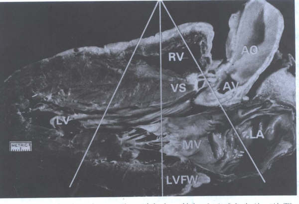
M-mode echocardiographic view
showing "ice-pick" views of selected areas of the
heart. One view displays the right ventricle (RV), aortic valve
(AV), portions of aorta (Ao), and left atrium (LA). Another
more apical view show the RV, ventricular septum (VS), left
ventricular cavity (LV), and left ventricular free wall (LVFW).
MV = mitral valve. (From BF Waller
et at. Tomographic views of normal and abnormal hearts: The
anatomic basis for various cardiac imaging techniques. Clin
Cardiol 13::804(pt l), 877(pt 11), 1990. Reproduced with permission
from th publisher and authors. )
Two-Chamber Method
The two-chamber method involves sectioning
the heart through the inflow tract of the left ventricle and
inflow and a portion of the outflow tracts of the right ventricle.
The plane of left ventricular sectioning is through the left
ventricle and left atrium in an anteroposterior fashion and
extending from base to apex. The two-chamber left ventricular
plane discloses views of left atrium, anterior (septal), and
posterior (mural) portions of the mitral valve leaflets, left
ventricular cavity, and the anterior, apical, and posterior
walls of the left ventricle. This view currently is used in
assessment of the left ventricle in patients with atherosclerotic
coronary heart disease. It provides another plane of sectioning
for classification of left ventricular damage. A parallel cut
on the right side of the heart discloses a similar view of the
right ventricular inflow (right atrium, tricuspid valve, right
ventricular body) but also discloses a portion of the right
ventricular outflow tract. Although this particular tomographic
view has been used less commonly in echocardiography, it would
appear to be ideal in assessing right ventricular wall damage,
intracavitary masses, and right ventricular outflow tract obstruction.
Four-Chamber Method
The four-chamber method involves sectioning
the heart from base to apex in a right-to-left plane along the
acute margins of right and left ventricles and corresponding
walls of the atria (Figs. 8, 22b, and 25). In the bisected specimen,
portions of the tricuspid valve (posterior and septal leaflet),
mitral valve (primarily posterior leaflet), AV valve annuli,
chordae tendineae, papillary muscles, and each of the four cardiac
chambers are visualized. In this view, it is readily apparent
that the tricuspid valve annulus is located more apical than
the mitral valve annulus. This anatomic finding is useful in
identification of the right ventricle in complex congenital
heart disease. Once the ventricle is identified, the AV valve
follows concordantly. The corollary is also true in that if
the AV valve can be morphologically identified, the ventricle
follows concordantly (i.e., recognition of the tricuspid valve
as the apical most AV valve also identifies the morphologic
right ventricle). The four-chamber view is useful in cardiomyopathies
for measurement of all four chambers and wall thickness and
for identification of cavitary thrombus or tumor.
Long-Axis Method
The long-axis method of cutting or imaging
the heart produces a unique left ventricular inflow/outflow
tract view (Figs. 6, 7, 8 ,14 , 26 , 27 and 31).
FIGURE 28
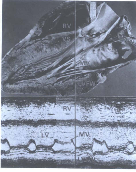
Parasternal long-axis view of heart
with correlating M-mode echocardiogram. The ice-pick view through
the midportion of the heart shows the right ventricle (RV) outflow
tract, the ventricular septum (VS), left ventricular (LV) cavity,
mitral valve (MV), and left ventricular free wall (LFVW). Systolic
measurements on M-mode echocardiogram correspond to measurements
on the formalin-fixed heart.
FIGURE 26
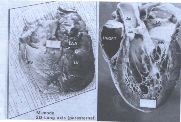
Tomographic sectioning of the heart
from base to apex along the planar lines shown in Fig. 2 produces
views that correlate with echocardiographic parasternal long-axis
images. Ao = aorta; AV = aortic valve; LA = left atrium; LAA
= left atrial appendage; LV = left ventricle; MV = mitral valve;
RV = right ventricle; RVOFT = right ventricular outflow tract;
VS = ventricular septum.
The Body (Thorax) as the Reference Axis
Tomographic sections of the heart obtained
by use of the body as the reference axisresult in cardiac images
that differ from those described earlier. Three standard anatomic
planes are generally used in CT and MRI: transverse (horizontal),
frontal (coronal), and parasagittal (paramedian) (Figs. 32 and
33). Corresponding anatomic cardiac sections produced by these
tomographic planes have been well illustrated in several anatomic
atlases.
Transverse (Horizontal) Method
Transverse tomographic planes of the thorax
produce sections of the heart with truncated or expanded views
of chambers and walls because of the oblique position of the
heart within the thorax (Figs. 31 and 33). Some of the transverse
views appear similar to the echo-cardiographic short-axis views.
Transverse sectioning at the level of the great vessels provides
an anatomic display of the pulmonary trunk and its bifurcation
into the right nd left main pulmonary arteries and an adjacent
cross section of the ascending aorta. Transverse sections taken
of the heart "from the head to the feet" produce a
family of oblique cross sections. One horizontal view produces
a foreshortened four-chamber view that when viewed from the
left, appears as a two-chamber echocardiographic cut and when
viewed from the right appears as a truncated view of right ventricular
inflow and an inflated view of the right atrium. Horizontal
planes are useful in evaluation of patients with coronary and
pericardial heart disease and in patients with diseases of the
great vessels (dissection, aneurysm, mediastinal masses).
FIGURE 29
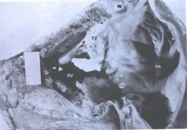
Tomographic cut of heart through right-sided
structures as viewed by a parasternal long-axis, two-dimensional
echocardiogram. RA = right atrium; RV = right ventricle; RVFW
= right ventricular free wall (anterior): RVPW = right ventricular
posterior wall: TV = tricuspid valve.
The left ventricular long-axis view is obtained
by sectioning the heart in an anterolateral plane from base
to apex. In this longitudinal plane, evaluation of the aortic
and mitral valves, proximal portion of the ascending aorta (sinus
portion and proximal tubular portion), left ventricular outflow,
left ventricular and atrial walls, and chamber is possible.
Also, a portion of right ventricular outflow tract just apical
to the pulmonic valve is viewed on the left ventricular long-axis
plane. The right-sided parallel longitudinal section views the
right atrium, tricuspid valve, and body of the right ventricle.
The left ventricular long-axis view is one of the "standard"
two-dimensional echocardiographic views of the heart and thus
is used for coronary, valvular, and myocardial heart disease.
The long-axis left ventricular section also corresponds to the
traditional M-mode echo-cardiographic image with "ice pick"
views of the aorta and left atrium, left ventricular outflow
tract and mitral valve, and proximal portion of the ventricular
septum, left ventricular cavity, and left ventricular free wall.
Anatomically, the left ventricular free wall imaged in this
plane represents the lateral left ventricular free wall.
Frontal (Coronal) Method
Frontal tomographic planes of the body (thorax)
produce the least familiar cardiac images compared with echocardiographic
images. Sectioning the thorax from the anterior to the posterior
(sternum to spine) results in cardiac sections that, at any
one time, contain portions of left and right ventricles, aorta
and pulmonary trunks, and left and right atria. These cardiac
sections also cut the heart obliquely, preventing adequate assessment
of chamber size and wall thickness or thinness. This method
provides excellent views of the right ventricular outflow tract,
pulmonary trunk, and pulmonary trunk bifurcation that are not
available in the previously described tomographic cardiac sections.
Also, the frontal plane is useful in evaluation of the aortopulmonary
window and the vena cava.
Parasagittal (Paramedian) Method
Parasagittal tomographic planes of the body
(thorax) produce another set of generally unfamiliar views of
the heart. Planes of sectioning cut the heart in right-to-left
fashion from shoulder to shoulder. Thus, the right-sided structures
(vena cavae, right atrium, right ventricle) are viewed last.
Some sections resemble the echocardiographic two-chamber views
of the right and left sides. This method also cuts chambers
and vessels in an oblique fashion that precludes adequate assessment
of chamber size and wall thickness in most images. This method
is excellent in anatomic evaluation of the aortic aneurysm,
dissection, and coarctation.
In addition to conventional transverse, corona!,
and sagittal imaging, oblique imaging planes are possible with
MRI.' Oblique planes permit cuts of the heart along its long
and short axes. The resultant cuts are analogous to the angiographic
right and left anterior oblique views.
The newer cardiac imaging modalities (MR1,
cine CT, positron emission tomography) not only provide depiction
of cardiac anatomy with the limitations mentioned above but
also provide an excellent technique for characterization of
myocardial tissue. Distinguishing ischemic and scarred myocardium,
tumor and fat infiltration, and intracavitary tumor versus thrombus
are useful morphologic data that cannot be assessed using present
echocardiographic modalities.
FIGURE 4-30
Tomographic sectioning of the heart
in a " breadloaf" fashion produces a series of short-axis
views of the left ventricle (LV) from apex to base. This "family
of ventricular slices" is seen in Fig. 9. A very basal
view of the heart (line A) produces a view of the aortic valve
(AV) (A). Line B corresponds to a basal view of the ventricles
(B) showing right ventricle (RV) and I.V, anterior (An) and
posterior (P) surfaces of the heart, and the ventricular septum
(VS)
Scintigraphic Thallium Imaging
Scintigraphic thallium testing is a popular
technique used in conjunction with exercise testing. Present
methods of sectioning the heart produce images that closely
resemble two-dimensional echocardiographic views yet are variants
of the oblique and sagittal planes. The similarity of these
images to that of the echocardiographic views results from using
the heart primarily as the axis for imaging.
FIGURE 31
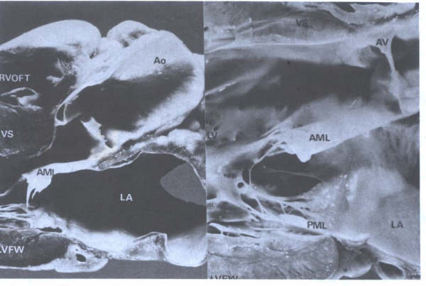
Parasternal long-axis view of the
heart as viewed on a two-dimensional echocardiogram. Left: This
view provides anatomic information about the basal ventricular
septum (VS). Left ventricular (L.V) cavity, and aortic ( AO)
and mitral (MV) valves. AML. = anterior mitral leaflet; Ao =
aorta; LA = left atrium; LVFW = left ventricular free wall:
RVOFT = right ventricular outflow tract. Right: Closeup view
of LV outflow tract showing fibrous continuity of AV and AML.
PML = posterior mitral leaflet.
FIGURE 4-32
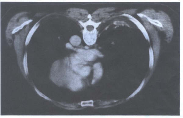
Transverse section of the heart from
a CT scan. The perpendicular cut of the thorax creates
oblique cuts of the heart.
FIGURE 4-33
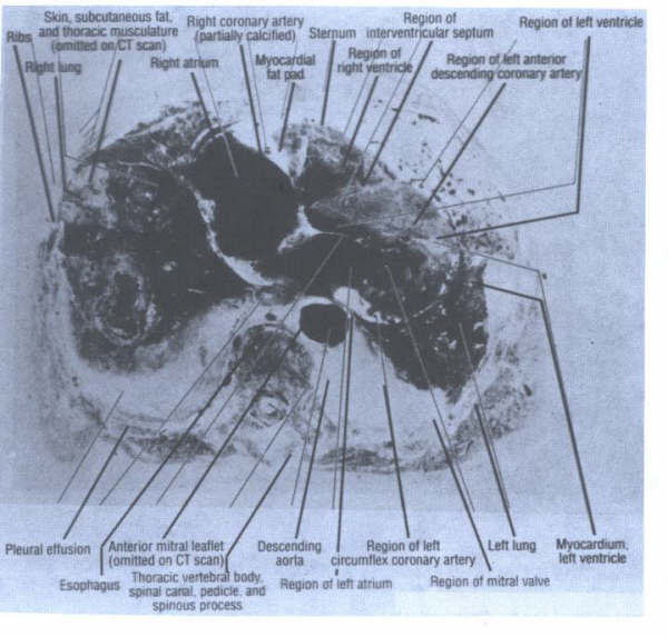
Transverse section of a human
cadaver thorax. Note the perpendicular cut through the thorax
produces truncated and expanded views of various cardiac structures.
The anterior left ventricular wall is much thicker than the
posterior wall due to the oblique cardiac section. The anterior
leaflet appears closer to the right atrium than to the left
atrium in this cut.
Figure 24
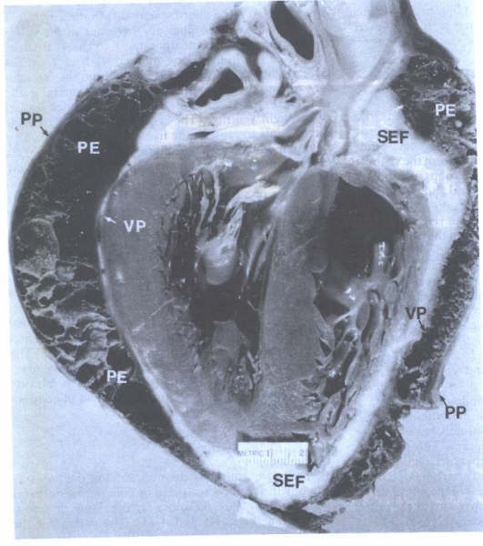
Fibrous pericardial effusion
(PE) helps to delineate the two normal layers of the pericardial
sac: visceral pericardium (VP) and parietal (PP). Subepicardial
fat (SEF) is located just beneath the visceral layer of pericardium.
FIGURE 25
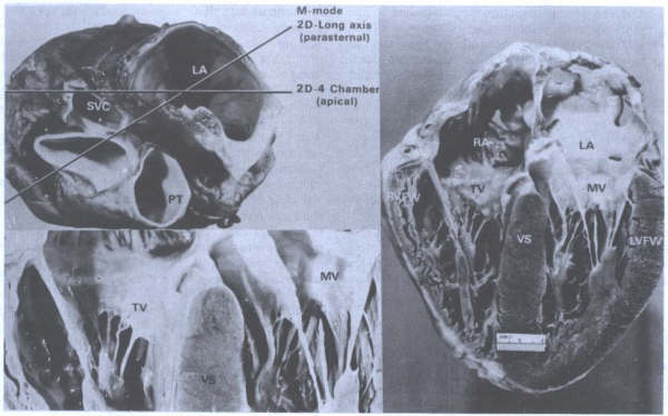
Composite showing method of
cutting a heart and resultant topographic views.
A. Basal view
of heart showing planes of base-apex sectioning in order to
obtain two-dimensional long-axis and two-dimensional, four-chamber
echocardiographic views. The parasternal long-axis view is also
used to correlate images obtained from M-mode echocardiography.
B. Closeup of four-chamber view showing atrioventricular valves
(tricuspid (TV), mitral valve (MV). The annulus of the TV is
located more apically than the MV annulus. VS = ventricular
septum. C. Four-chamber view of heart. LA = left atrium; LVFW
= left ventricular free wall: RA = right atrium; RVFW = right
ventricular free wall. (From BF
Waller: Morphologic aspects of valvular heart disease: Part
I. Curr Prob Cardiol IX:13. 1985. Reproduce